8-2
Adjustment Windows and Run Win-
dows
After test measurement and remeasurement are performed on the Main Window (layout 0), check the
measurement results. If there are problems, adjust the processing item setting values of the process-
ing units. When the measurement results are stable, change to the Main Window (layout 1) and per-
form measurements. This section describes the adjustment windows and run windows.
8-2-1
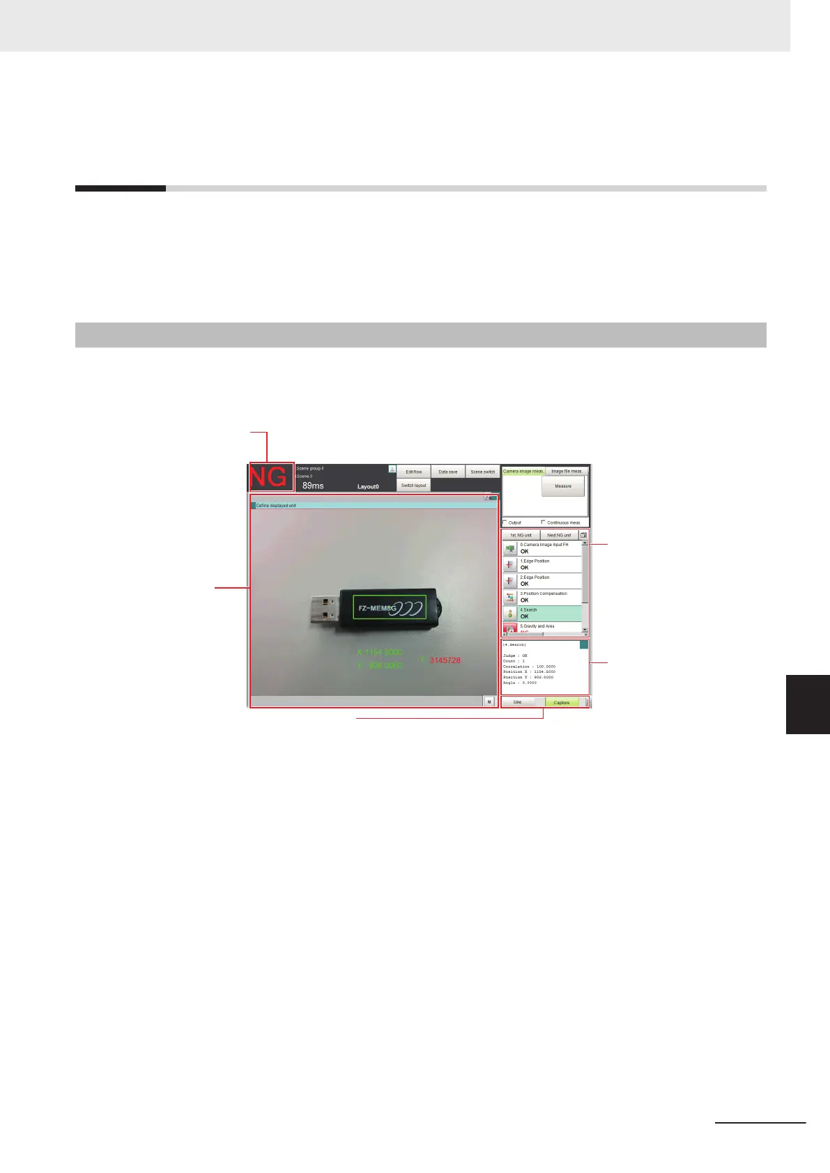
Main Window (Layout 0): Adjustment Window (Default)
Layout 0 is set as an adjustment window by default. (This can be changed in Layout Modification
Mode.)
The judgement
result and
measurement time
for the entire scene
are displayed.
Units with NG
results are
displayed in
red.
Measurement
results are
displayed in
text format.
ou can overlay
the measurement
results on the
Camera image.
Measurement Manager Bar
This is displayed regardless of the layer that is displayed.
• Capture:
Saves the contents that is displayed on the monitor as an image.
Refer to 3-5 Capturing Screen Images on page 3 - 29.
• LCD Off: (Displayed only with LCD-integrated Controllers.)
Turns OFF power to the LCD monitor.
Refer to .
• Line: (This is displayed only when the operation mode is set to Multi-line Random-trigger Mode.)
This changes the line.
Refer to Multi-line Random-trigger Mode on page 4 - 18.
• Switch Screen: (This is displayed only when the operation mode is set to Non-stop Adjustment
Mode.)
This changes to the Non-stop Adjustment Mode Window.
Refer to Non-stop Adjustment Mode on page 4 - 23.
• M:
This button opens the window to show the amount of memory and percentage of memory used.
Refer to 3-4 Checking the Memory Consumption and Percentage of Memory Used on page 3 - 28.
8 Setting Windows
8 - 9
FH/FHV Series Vision System User’s Manual (Z365-E1)
8-2 Adjustment Windows and Run Windows
8
8-2-1 Main Window (Layout 0): Adjustment Window (Default)

 Loading...


