Using Alignment
l
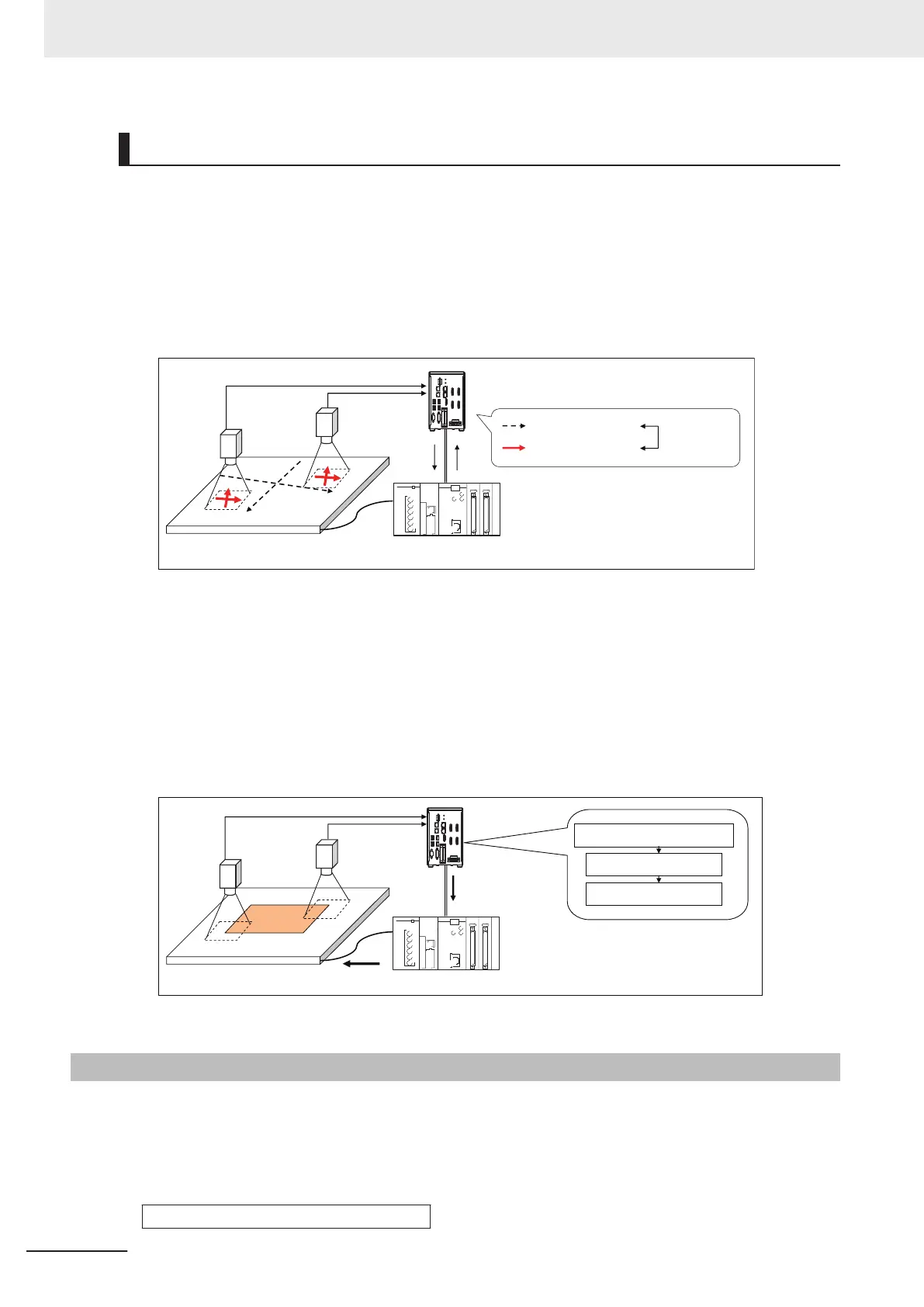
Calibration
The Camera and external device both have their own coordinates, so it is necessary to calculate
the relationship of the coordinates of the Camera and the external device in advance. This process
is called calibration.
The FH/FHV series Controller uses the external device to move the workpiece and measure it. This
is repeated to calculate the calibration parameter.
Sensor Controller
PLC
: Stage coordinates
: Camera coordinates
Association
(Execution of
calibration)
Stage
Camera 1
Camera 0
l
Alignment: Aligning the Position of the Workpiece
The image taken by the Camera is used to measure the position of alignment marks on the work-
piece, or the position of specific features of the workpiece (such as corners) in Camera coordinates
(pixels). The calibration parameter that is calculated in the calibration flow is used to convert the
measured position into the coordinates of the external device. Finally, the axis movement that is
required to match the measured position to the reference position angle is calculated and output to
the external device.
Camera 1
Camera 0
Sensor Controller
PLC
Alignment calculations
Calibration Data Reference
Result output
Movement command to reference position
Stage
Calculation and
output of the required
axis movement
10-9-2
Execution of Calibration
This section uses two Cameras and a stage as the external device to describe an example for setting
the calibration flow and executing calibration.
Example: Calibration Flow Example for 2 Cameras
Camera Image Input processing item
Select Camera 0.
10 Advanced Usage
10 - 54
FH/FHV Series Vision System User’s Manual (Z365-E1)

 Loading...


