2-1
Basic Mechanism for Measurements
An FH/FHV series Sensor Controller uses pre-built packages that contain all the processing tasks (for
image input, measurement processing, displays, outputs, etc.) that are required for vision inspections.
You arrange these packaged processes in order of execution of the vision inspection.
An FH/FHV series Controller executes vision inspections according to user-created flows.
Precautions for Correct Use
In the FH/FHV, a flow that contains packaged processes that are arranged in order of execution
of processing items and image processing is called a measurement flow.
Processing items and measurement flows can have more than one setting. You can switch the
setting based on the scene to inspect.
For details, Refer to Section 5 Creating Measurement Scenes on page 5 - 1
Concept of Measurement Processing
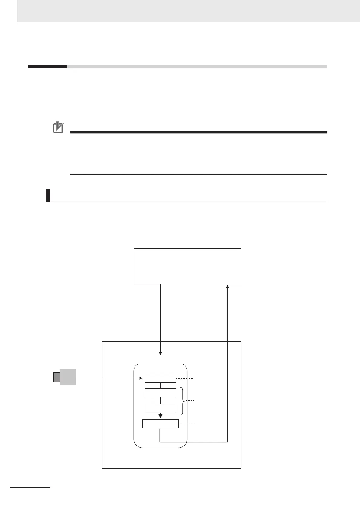
When the FH/FHV receives a measurement trigger from the PLC or other external device, the image
input from a Camera, measurement processing, and output of measurement results (e.g., OK/NG
judgement results) are executed in the order that those processing items are registered in the meas-
urement flow.
PLC or other external device
Image Input
Defect
Search
Measurement flow
FH
Output Unit
Camera
Measurement
trigger
The measurement flow is executed basically in
order of the unit numbers.
Measurement
results are
output.
Measurement
processing of
the input image
Image input
from the
Camera
• Judgement
result
• Measured
values
2 Features
2 - 2
FH/FHV Series Vision System User’s Manual (Z365-E1)

 Loading...


