4-11
Setting the Pulse Width for the STEP
Input Detection [STEP Signal Filter
Setting]
You can set a filter as a countermeasure against STEP input chattering and to prevent operation mal-
functions due to noise.
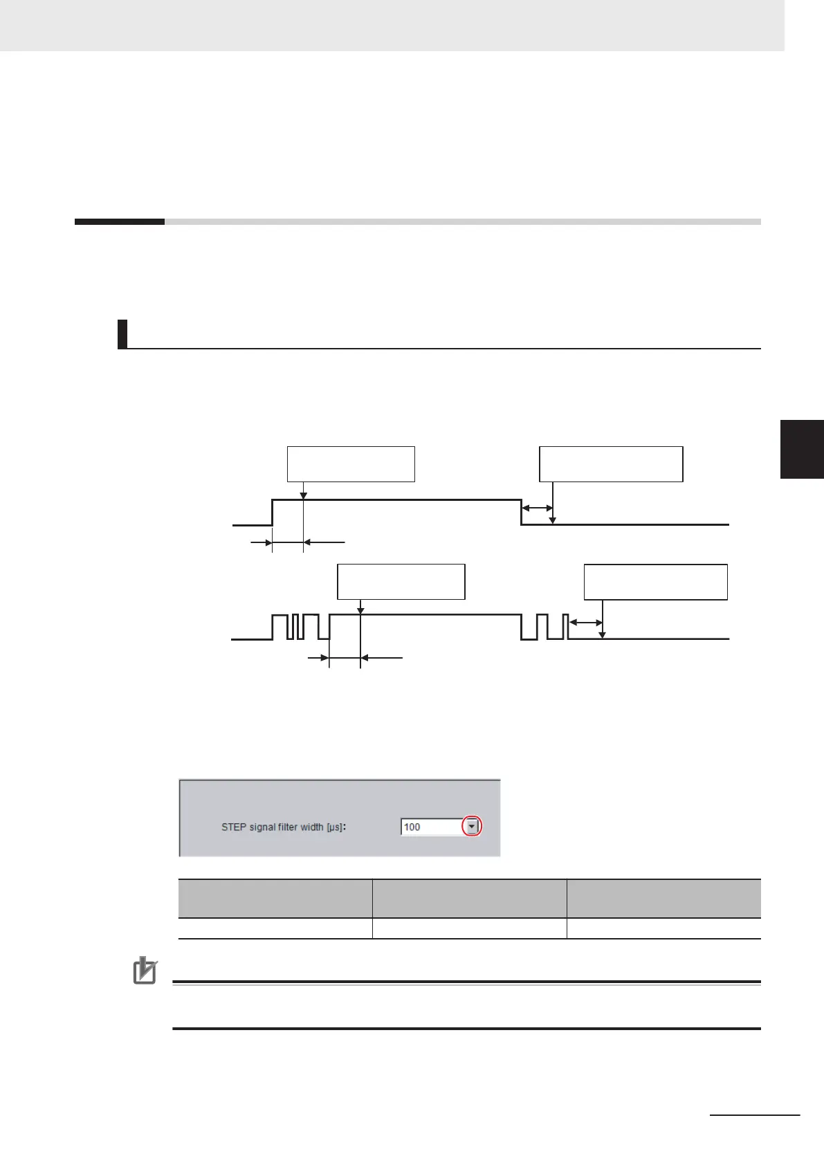
Filter Set Value of 100 μs (Default Value)
The STEP signal is detected as being ON at the point it is ON continuously for at least 100 μs, and
measurement begins at that point. Accordingly, STEP signal detection is delayed by an amount of time
equivalent to the set filter value. Also, when turning from ON to OFF, the OFF filter at 100 μs is activat-
ed and the STEP signal is detected as OFF when it is OFF for at least 100 μs.
ON
OFF
STEP
ON
OFF
STEP
(1) If there is no input chattering
100 µs
(2) If there is input chattering
100 µs
ON is detected when the
signal stays ON for at least
100 µs.
ON is detected when the
signal stays ON for at least
100 µs.
OFF is detected when the
signal remains OFF for 100 µs.
OFF is detected when the
signal remains OFF for 100 µs.
100μs
100μs
1 In the Main Window, select System settings - Other - STEP setting from the Tool menu.
2 Set the filter width in the STEP setting area.
Item
Set value
[Factory default]
Description
STEP signal filter width [μs] [100], 200, 300, 400, 500 Set the filtering width.
Precautions for Correct Use
If you use Multi-line Random-trigger Mode, the value for the STEP signal filter on line 0 is ap-
plied to all lines.
4 Setting the Controller
4 - 49
FH/FHV Series Vision System User’s Manual (Z365-E1)
4-11 Setting the Pulse Width for the STEP Input Detection [STEP Sig-
nal Filter Setting]
4

 Loading...


