Setting up Compax3 C3I22T11
158 192-120114 N5 C3I22T11 June 2008
Structure:
Master Z1 MasterPos Gearing numerator Slave - N2 Slave_U Load
N1 Gearing denomi-
nator
Units Z2 to motor
Gearbox
Detailed structure image
with:
Z1
Travel Distance per Master Axis revolution
(M_Units/rev)
MD =
N1
*
Travel Distance per Master Axis revolution
- Denominator
Entry in the ”configuration
of the signal source” wizard
Z2
Travel path per revolution slave axis nu-
merator
SD =
N2
*
Travel path per revolution slave axis de-
nominator
Entry in the ”configuration
of the signal source” wi-
zard
MD:
Feed of the master axis
SD:
Feed of the slave axis
4.2.1.3 +/-10V analog speed setpoint value as signal source
Via Analog channel0 (X11/9 and X11/11) the speed of the master is read in.
From this value a position is internally derived, from which then the motion of the
drive is derived with reference to the transmission ratio.
Without limitation effect applies:
Velocity of the master * (Gearing numerator / gearing denominator) = velocity of
the slave
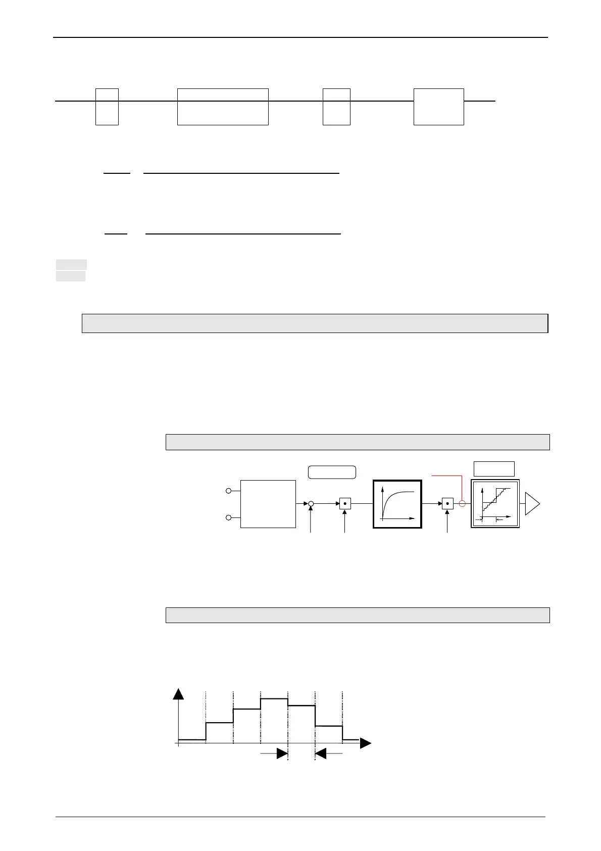
Signal processing of the analog input 0
685.3
170.3
170.2
170.2
+
170.4
X11/9 +
X11/11-
Actual
value
monitoring
Analog 0
B
Precise
interpolation
T
B: Continuative structure image (see page 237)
The reference to the master is established with the velocity at 10V.
If required the direction of rotation of the master axis read in can be changed.
Time grid of master signal source
Averaging and a following filter (interpolation) can help to avoid steps caused by
discrete signals.
If the external signal is analog, there is no need to enter a value here (Value = 0).
For discrete signals e.g. from a PLC, the scanning time (or cylce time) of the signal
source is entered.
T
t
This function is only available if the analog interface +/-10V is used!
 Loading...


