Parker EME
Compax3 device description
192-120114 N5 C3I22T11 June 2008 55
3.6.4. Motor / Motor brake C3H
Motor connection clamps
PIN Designation
M1/U U (motor)
M2/V V (motor)
M3/W W (motor)
PE PE (motor)
A motor output filter is required for motor cables >50m. Please contact us.
Shielding connection of the motor cable
The motor cable should be fully screened and connected to the Compax3 housing.
The shield of the motor cable must also be connected with the motor housing. The
fixing (via plug or screw in the terminal box) depends on the motor type.
Motor holding brake!
Connect the brake only on motors which have a holding brake! Otherwi-
se make no brake connections at all.
Requirements cables for motor holding brake
If a motor holding brake is present, a cable of the motor holding brake
must be fed on the device side through the toroidal core ferrite provided
as accessory ZBH0x/xx (63Ω @1MHz, di=5.1mm), in order to ensure
error-free switching on and off of the motor holding brake.
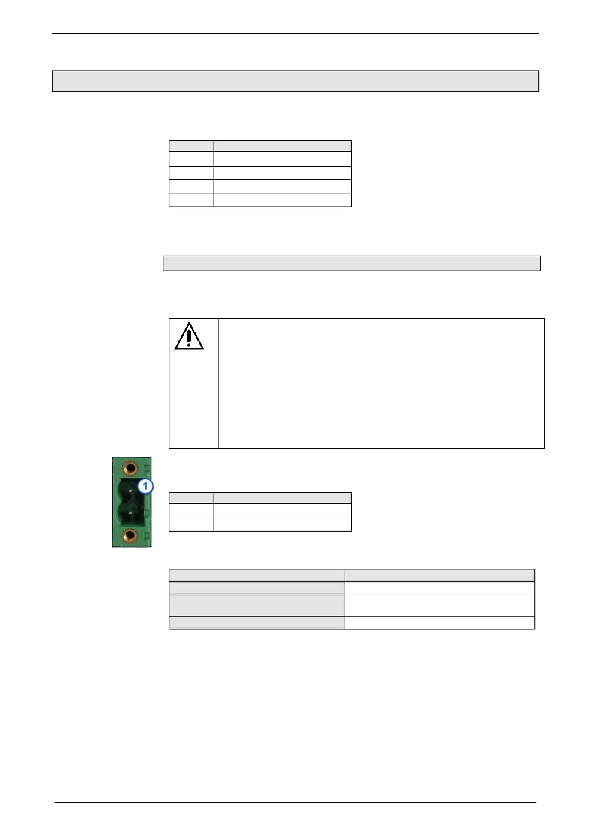
Connection of motor brake X3
PIN Designation
1 BR
2 GND
Motor holding brake output
Motor holding brake output Compax3
Voltage range
21 – 27VDC
Maximum output current (short circuit
proof)
1.6A
Minimum output current
150 mA
Requirements for
Compax3H motor
cable
 Loading...


