Setting up Compax3 C3I22T11
192 192-120114 N5 C3I22T11 June 2008
stability, attenuation
In this chapter you can read about:
Stability problem in the high-frequency range: ................................................................ 192
Stability problem in the low
-frequency range:.................................................................. 192
In general, two stability problems may occur in a servo drive control:
Stability problem in the high-frequency range:
The "control structure" figure shows that the reverse effect in the control loop (ne-
gative feedback) is a prerequisite for the functioning of a control system. Due to the
delay in signal transmission, the effect of the negative feedback is diminished or
even compensated. The reason is that the corrective measures of the controller are
also delayed in the event of delayed signal transmission. This results in a typical
oscillating course of the control variable. In the worst case, the deviation of the
control variable and the effect of the corrective measures get in phase, if the delays
reach a defined value. The negative feedback passes into positive feedback. If the
product of the gain factors of all control loop components is higher than 1, the oscil-
lation amplitude will continually rise.
In this case the control loop is unstable. In the total gain of 1 the oscillation keeps
its amplitude and the control loop is within the limits of stability. The transient re-
sponse can be characterized by the attenuation and the transient time (velocity).
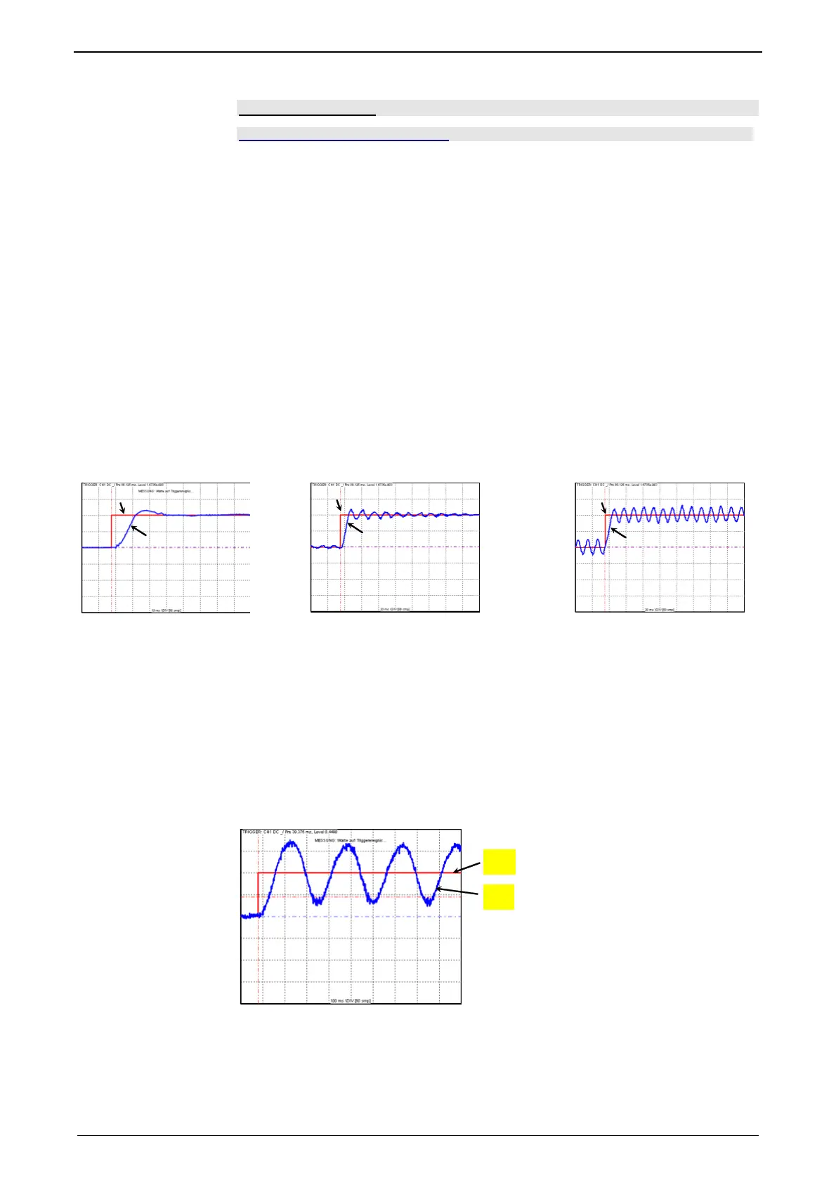
Step response of a stable controller and of a controller approaching the stability limit
w
x
w
x
x
w
Stable
Well attenuated
Stable
Poorly attenuated
Stability limit
not attenuated
W: Setpoint value
x: Actual value
Stability problem in the low-frequency range:
In this case the controller was set for a very inert control path, while the actual con-
trol path is much more dynamic. The controller reacts to a disturbance variable with
a much too strong corrective measure so that the disturbance variable is overcom-
pensated and even an increasing oscillation may be the result. In this case the
mechanic system of the control path may be destroyed.
Velocity jerk response (low-frequency stability limit)
2
1
1: Setpoint speed value
2: Actual speed value
 Loading...


