Compax3 device description C3I22T11
50 192-120114 N5 C3I22T11 June 2008
3.6 Connections of Compax3H
In this chapter you can read about:
Compax3H plugs/connections............................................................................................50
Terminal clamps – max. line cross section C3H ................................................................52
Plug and pin assignment C3H............................................................................................53
Motor / Motor brake C3H....................................................................................................55
Control voltage 24 VDC C3H..............................................................................................56
Mains connection Compax3H.............................................................................................57
Braking resistor / supply voltage C3H ................................................................................57
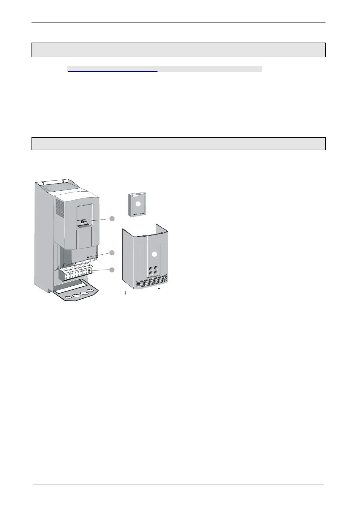
3.6.1. Compax3H plugs/connections
The following figure is an example for all sizes.
The fitting of the different controller plugs depends on the extension level of Com-
pax3.
3
5
4
1
2
(1): Dummy cover with display of the external device
status LEDs.
(2): lower clamp cover, fixed by 2 screws at the device
bottom.
(3): RS232 programming interface
Connection to the PC via adapter cable SSK32/20 (furni-
shed with the device) and standard RS232 cable SSK1.
(4): Controlling
(5): Power connections
 Loading...


