Setting up Compax3 C3I22T11
188 192-120114 N5 C3I22T11 June 2008
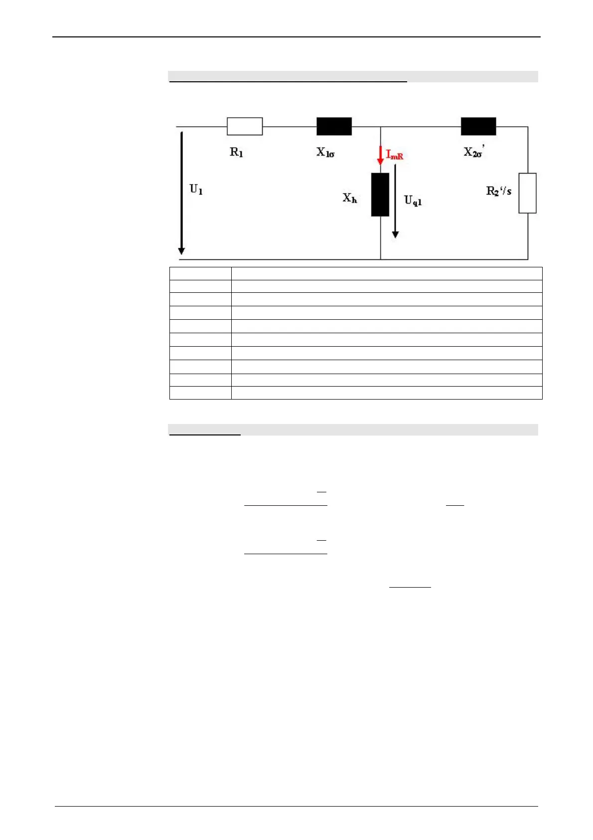
Replacement switching diagram - data for a phase
This data can be obtained from the manufacturer or be determined by measure-
ment.
U1: Nominal phase voltage
R1: Stator leg resistance
X1σ=2πfL1σ:
Leak reactance (for f=50Hz mains frequency)
L1σ:
Stator leakage inductance
X
h
=2πfL
H
:
Main reactance (for f=50Hz mains frequency)
LΗ:
Main field inductance
X2σ'=2πfL2σ:
Referenced leak reactance (for f=50Hz mains frequency)
L2σ:
Rotor leak inductance
R
2
': Referenced carriage resistance
I
mR
: Magnetization Current
Slip Frequency
The slip frequency is stated in [hz electrical] or in [‰] and can be determined as
follows
f2[mHz (electrical)]= (fs*60-Nnominal*P/2)/N
1000
60
2
60
][Pr
1000
120
1000
60
2
60
.)]([
2
2
⋅
⋅
⋅−⋅
=
⋅
⎟
⎠
⎞
⎜
⎝
⎛
⋅−=⋅⋅
⋅
⋅−⋅
=
S
NennS
NennSS
S
NennS
f
P
Nf
omillef
P
Nff
f
P
Nf
elmHzf
Whereas P = value before the point of the term è
Nenn
s
N
f 260⋅
f
s
: Synchronous nominal frequency (dimensioning base)
N
Nominal
: Nominal speed in rpm
f
2
: Slip frequency in mHz (electrical)
 Loading...


