Compax3 device description C3I22T11
66 192-120114 N5 C3I22T11 June 2008
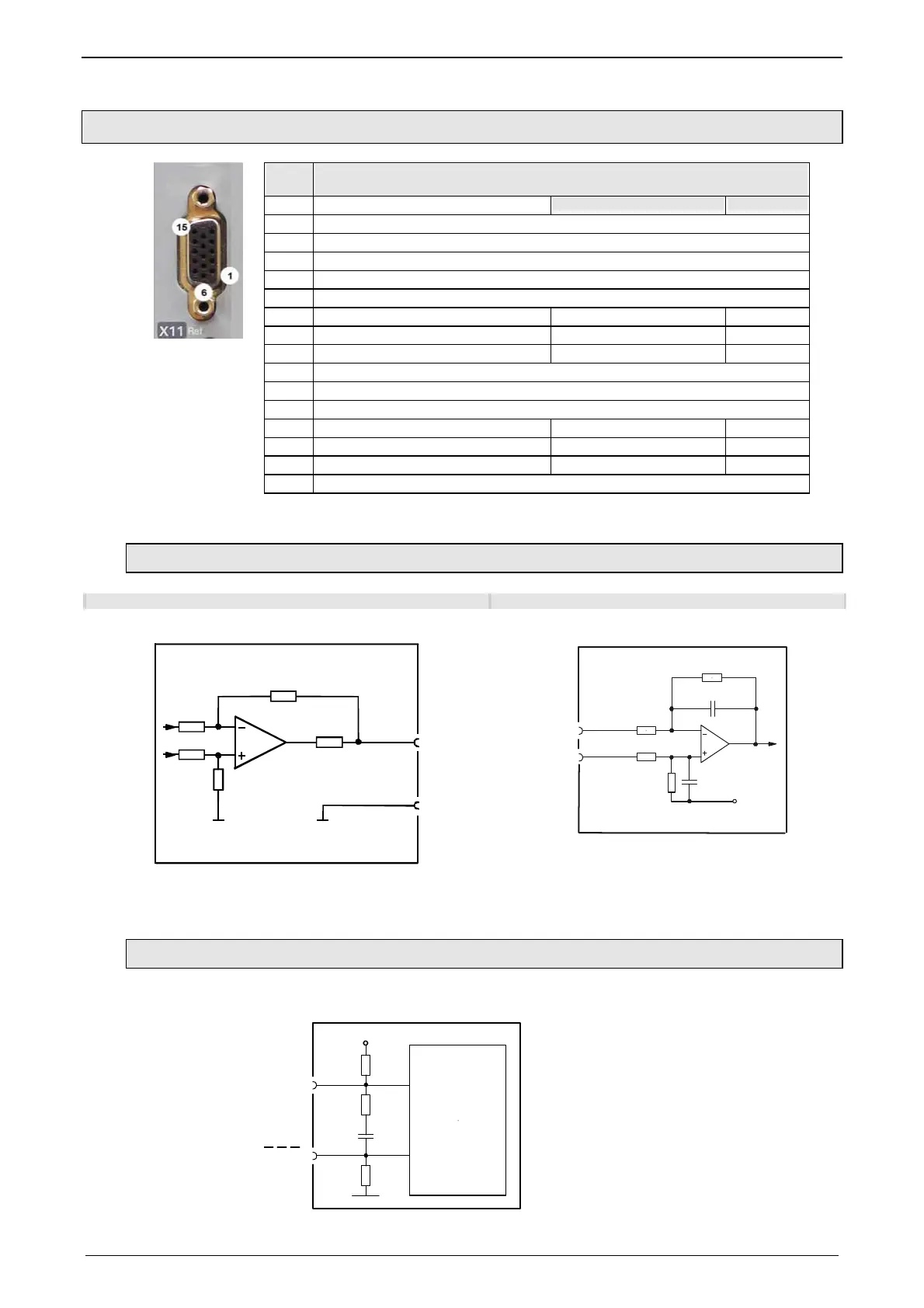
3.8.2. Analog / Encoder (plug X11)
PIN
X11
Reference
High Density Sub D
Encoder SSI
1 +24V (output) max. 70mA
2 Ain1 -: analog input - (14Bit; max. +/-10V)
3 D/A monitor channel 1 (±10V, 8-bit resolution)
4 D/A monitor channel 0 (±10V, 8-bit resolution)
5 +5V (output for encoder) max. 150mA
6 - Input: steps RS422 (5V - level) A/ (Input / simulation) Clock-
7 + Input: steps RS422 (5V - level) A (Input / simulation) Clock+
8 + Input: direction RS422 (5V - level) B (Input / simulation)
9 Ain0 +: analog input + (14Bit; max. +/-10V)
10 Ain1 +: analog input + (14Bit; max. +/-10V)
11 Ain0 -: analog input - (14Bit; max. +/-10V)
12 - Input: direction RS422 (5V - level) B/ (Input / simulation)
13 Reserved N/ (Input / simulation) DATA-
14 Reserved N (Input / simulation) DATA+
15 GND
Technical data X11 (see page 401)
3.8.2.1 Wiring of analog interfaces
Output Input
Compax3
+/-10V/1mA
(max: 3mA)
X11/3
X11/15
332
X11/4
10nF
2.2KΩ
10KΩ
in+
2.2KΩ
X11/9
10KΩ
10nF
in-
X11/11
2.5V
Compax3
Please note: with Ain- on earth and Ain+ open,
2.02V are read in.
Structure image of the internal signal processing of the analog inputs,
Ain1 (X11/10 and X11/2) has the same wiring!
3.8.2.2 Connections of the encoder interface
10nF
+5V
121
Ω
1K
Ω
1
K
Ω
GND
BN
RS422
Transceiver
BN
Compax3
The input connection is available in triple (for A & /A, B & /B, N & /N)
 Loading...


