Parker EME
Compax3 device description
192-120114 N5 C3I22T11 June 2008 47
3.5.7. Braking resistor / temperature switch Compax3MP (mains
module)
The energy generated during braking operation must be dissipated via a braking
resistor.
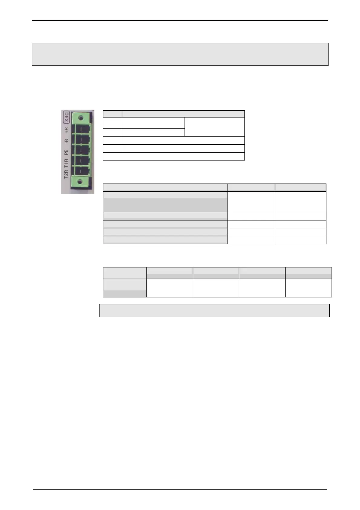
Connector X40
PIN Description
+R + Braking resistor
-R - Braking resistor
no short-circuit protec-
tion!
PE PE
T1R Temperature Switch
T2R Temperature Switch
Braking operation Compax3MPxxD6 (mains module)
Device type Compax3 MP10 MP20
Capacitance / storable energy
550µF/
92Ws at 400V
53Ws at 480V
1175µF/
197Ws at 400V
114Ws at 480V
Minimum braking- resistance
27Ω 15Ω
Recommended nominal power rating
500 ... 1500W 500 ... 3500W
Pulse power rating for 1s
22kW 40kW
Maximum permissible continuous current
13A 15A
Braking operation Compax3MxxxD6 (axis controller)
Device type
Compax3
M050 M100 M150 M300
Capacitance /
storable energy
110µF/
18Ws at 400V
10Ws at 480V
220µF/
37Ws at 400V
21Ws at 480V
220µF/
37Ws at 400V
21Ws at 480V
440µF/
74Ws at 400V
42Ws at 480V
Maximum capacity in the axis combination: 2400µF
Connection of a braking resistor on Compax3MP (mains module)
Mimimum line cross section: 1.5mm
2
Maximum line length: 2m
Maximum intermediate circuit vol-
tage:
810VDC
Switch-on threshold: 780VDC
 Loading...


