Parker EME
Setting up Compax3
192-120114 N5 C3I22T11 June 2008 167
4.3.2.3 Example: Setting the Oscilloscope
SINGLE measurement with 2 channels and logic trigger on digital in-
puts
The order of the steps is not mandatory, but provides a help for better understan-
ding.
As a rule, all settings can be changed during a measurement. This will lead to an
automatic interruption of the current measurement and to a re-start of the measu-
rement with the new settings:
Assumption: A test movement in the commissioning mode is active.
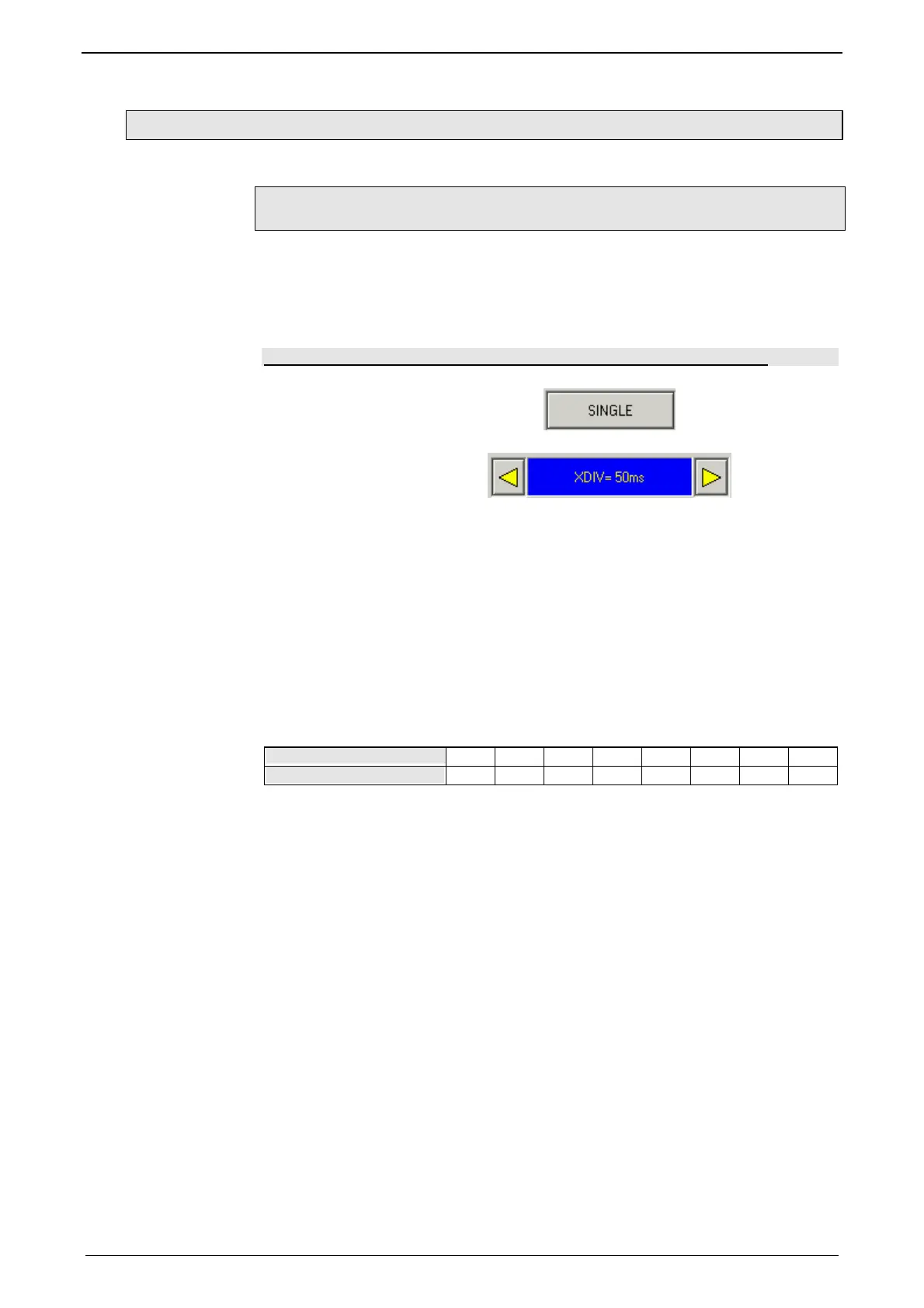
1.) Select OSCI operating mode
2.) Select Time basis XDIV
3.) Select channel 1 signal source digital inputs 120.2 from status tree with
the aid of Drag & Drop
4.) Select channel 2 (filtered actual speed) via "Drag and drop" from the sta-
tus tree
5.) Set trigger to channel 1 and DG.
Input of the mask in HEX
Triggering a rising edge to input I1.
BIT 0 (value 1) = I0
BIT 1 (value 2) = I1
BIT 2 (value 4) = I2 etc.
Trigger to input
I0 I1 I2 I3 I4 I5 I6 I7
Trigger mask in hex
1 2 4 8 10 20 40 80
The masks can also be combined so that the trigger is only active, if several inputs
are active. Example: Triggering to I2 and I5 and I6 -> 4h + 20h + 40h = 64h
The mask for input I1 is in this case 2.
select rising edge.
Note: If the trigger mask DG (digital) is selected for a channel, the display mode of
the trigger channel is automatically set to DIG display.
6.) Start measurement
7.) Set pretrigger in the OSCI window
Note: There is no level for the DIG trigger The the event lomit determines the mask
If a trigger event occurs, the measurement values are captured until the measure-
ment is completed.
Afterwards, the measurement values are read from the Compax3 and displayed.
The display mask of trigger channel 1 was not yet limited, therefore it shows all 16
bit tracks (b0...b15). In order to limit it to 8 bit tracks, you must call up the menu for
channel 1 via [CH1] and select "change logic of display mask [H].
Limit the display mask to 8 bit tracks with Mask FFh.
In the display the bit tracks b0 to b7 are now shown: