Parker EME
Compax3 device description
192-120114 N5 C3I22T11 June 2008 31
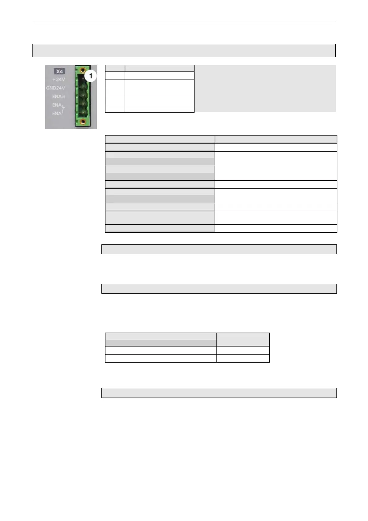
3.3.3. Control voltage 24VDC / enable connector X4 C3S
PIN Description
1 +24V (supply)
2 Gnd24 V
3 Enable_in
4 Enable_out_a
5 Enable_out_b
Line cross sections:
minimum: 0.25mm
2
maximum: 2.5mm
2
(AWG: 24 ... 12)
Control voltage 24VDC Compax3S and Compax3H
Controller type Compax3
Voltage range
21 - 27VDC
Mains module
with switch-on current limitation, due to capaci-
tive load
Fuse
MCB miniature circuit breaker or "delayed ac-
tion fuse", due to capacitive load
Current drain of the device
0.8A
Total current drain
0.8 A + Total load of the digital outputs + cur-
rent for the motor holding brake
Ripple
0.5Vpp
Requirement according to safe extra
low voltage (SELV)
yes
Short-circuit proof
conditional (internally protected with 3.15AT)
Hardware - enable (input X4/3 = 24VDC)
This input is used as safety interrupt for the power output stage.
Tolerance range: 18.0V - 33.6V / 720Ω
Safe standstill (X4/3=0V)
For implementation of the "Safe standstill" safety feature in accordance with the
”protection against unexpected start-up” described in EN1037. Observe instructi-
ons in the corresponding section (see page 78) with the circuitry examples!
The energy supply to the drive is reliably
shut off, the motor has no torque.
A relay contact is located between X4/4 and X4/5 (normally closed contact)
Enable_out_a - Enable_out_b Power output
stage is
Contact opened activated
Contact closed disabled
Series connection of these contacts permits certain determination of whether all
drives are de-energized.
Relay contact data:
Switching voltage (AC/DC): 100mV -60V
Switching current: 10mA - 0.3A
Switching power: 1mW...7W
 Loading...


