Parker EME
Compax3 device description
192-120114 N5 C3I22T11 June 2008 67
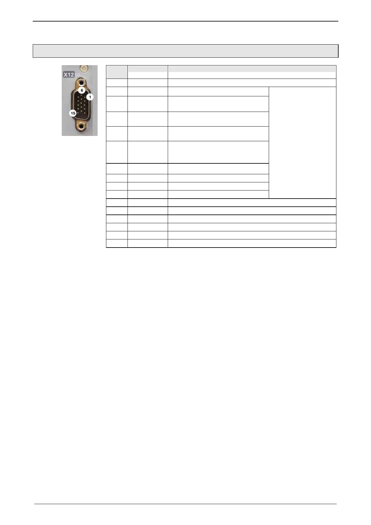
3.8.3. Digital inputs/outputs (plug X12)
PIN
X12
Input/output High density/Sub D
1 A +24VDC output (max. 400mA)
2 O0 No Error
3 O1
Position / speed / gear synchronization
attained (max. 100mA)
4 O2
No power output stage current (max.
100mA)
5 O3
Axis stationary with current, with set-
point 0 (max. 100mA)
6 I0="1": Quit (positive edge) / Energize the axis
The address of the current motion set
is read in new.
I0="0" Deenergize axis with delay
7 I1 No stop
8 I2 JOG +
9 I3 JOG -
Only for "fixed as-
signment"
Functions are availa-
ble, if "Fixed as-
signment" was selec-
ted for the I/O as-
signment in the confi-
guration wizard
10 I4 Reg input
11 E 24V input for the digital outputs Pins 2 to 5
12 I5 Limit switch 1
13 I6 Limit switch 2
14 I7 Machine reference initiator
15 A Gnd 24 V
All inputs and outputs have 24V level.
Maximum capacitive loading of the outputs: 30nF (max. 2 Compax3 inputs can be
connected)
Input-/Output extension (see page 389)
The display o
f the digital inputs in the optimization window of the C3 ServoManager
does not correspond to the physical status (24Volt=on, 0Volt=off) but to the logic
status: If the function of an input or output is inverted (e.g. limit switch, negatively
switching), the corresponding display (LED symbol in the optimization window) is
OFF with 24Volts at the input and ON with 0 Volts at the input.
In operation via DeviceNet the inputs I0 ... I3 as well as the outputs O0 ... O3 can
be freely assigned as an option.
Configurable via the C3 ServoManager (configuration: Operating mode / I/O assi-
gnment)
Optimization win-
dow display
 Loading...


