Compax3 device description C3I22T11
90 192-120114 N5 C3I22T11 June 2008
3.11.2. STO function on the Compax3M
In this chapter you can read about:
Safety switching circuits .....................................................................................................90
Safety notes and limitations of the STO function in the Compax3M ..................................91
Technical details of the Compax3M S1 option ...................................................................92
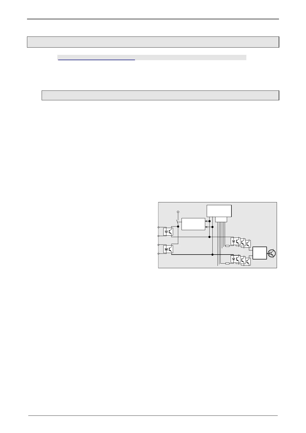
3.11.2.1 Safety switching circuits
The current flow in the motor windings is controlled by a power semiconductor
bridge (6-fold IGBT). A processor circuit and PWM circuit will switch the IGBT with
rotary field orientation. Between control logic and power module, optocouplers or
pulse transmitters are used for potential separation
On the Compax3M drive controller with S1 option, the X14 (STO) connector can be
found on the front plate. 2 optocouplers are controlled on two channels via the
STO1/ and STO2/ terminals of this connector. When requesting the STO via an
external safety switching device, the two auxiliary voltage supply channels of the
power stage control circuits are switched off on two channels. Therefore the power
transistors (IGBTs) for the motor current can not longer be switched on.
The hardware monitor detects a failure of the optocoupler circuit of a channel by
always checking both channels for similarity. If the hardware monitor detects a
discrepancy for a defined time (max. 20s), the error will be stored in the hardware
latch The processor signals this error externally via the 0x5493 error code. An acti-
vation of the coupler supply can then only take place via a hardware reset (swit-
ching off and on again) of the device.
*
X14.4 STO_GND
X14.3 STO2/
X14.2 STO-GND
X14.1 STO1/
Hardware-
Monitor
+5V
Controller
Software
6 IGBT
Driver
PWM
Compax3M ...S1
* Potential separation with optocoupler.
 Loading...


