Setting up Compax3 C3I22T11
206 192-120114 N5 C3I22T11 June 2008
Symbol Description
p
K
Proportional term
signal is multiplied with K
p
T1
First order delay component (P-T1 component)
K
I
Integration block (I-block)
Kp,T
N
PI-block
Limitation block (signal limitation)
f
f
B
d
Notch filter (band elimination filter)
Addition block
blue descrip-
tion
Optimization objects
(simple pointer line)
red descripti-
on
Status objects
(pointer line with vertical stroke)
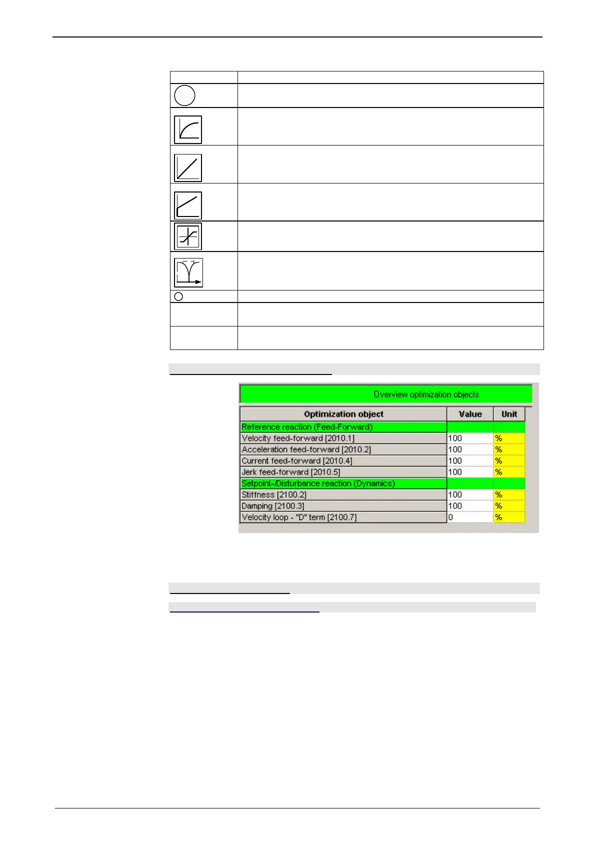
Standard optimization parameters
The above figure shows the parameters for the standard group. With the aid of
these parameters, you can optimize the standard cascade structure.
Control signal limitations
In this chapter you can read about:
Limitation of hte setpoint velocity..................................................................................... 207
Limitation of the setpoint current...................................................................................... 207
Limitation of the control voltage ....................................................................................... 207
The cascade structure shows that a limitation block is available in the control signal
sector of each controller. The limitations of the position and velocity loops are cal-
culated from the set limitations in the configuration and the motor parameters of the
selected motor.
 Loading...


