Parker EME
Setting up Compax3
192-120114 N5 C3I22T11 June 2008 195
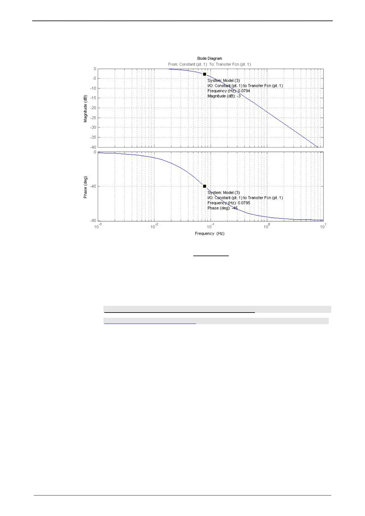
Frequency response of the P-TE component (value and phase)
The cutt-off frequency
Hz
T
f
E
0795,0
2
1
0
=
⋅
=
π
is the fre-
quency where the input signal is attenuated by 3dB (-3dB attenuation). The phase
shift between the output and the input is -45° at this frequency.
Precisely this cut-off frequency is called the bandwidth of a control loop.
Setpoint and disturbance behavior of a control loop
In this chapter you can read about:
Demand behavior ............................................................................................................ 196
Disturbance behavior....................................................................................................... 196
Test functions .................................................................................................................. 196
Characteristics of a control loop setpoint response
......................................................... 197
The setpoint behavior is the behavior of the control loop for the setpoint variable W.
We assume that the disturbance variable Z=0.
The disturbance behavior describes the behavior of the control loop for disturbance
variable Z. In this case, we assume, in analogy to the setpoint behavior, that the
setpoint variableW=0.
 Loading...


