Setting up Compax3 C3I22T11
224 192-120114 N5 C3I22T11 June 2008
controller bandwidth (velocity loop) and the center frequency is long enough (at
least factor 5). This permits to deduce the following recommendation:
4 xor 1x
][17.22102
5000000
.2150
==
⋅
≥
µsO
xO
π
Obj2210.17: Recplacement time constant of the velocity loop in µs.
If this distance is too small, the stability of the control can be very negatively in-
fluenced!
Bandwidth filter 1 (O2150.2) / bandwidth filter 2 (O2150.5)
This defines the width of the notch filter.
The value refers to the entire frequency band, where the attenuation of the filter is
higher than (-)3dB.
In practice it shows that even if there is enough distance towards the control, it can
be negativley influenced by too high bandwidths (higher than 1/4 of the center fre-
quency).
5 xo
2x
4
4/1.2150
.2150
=
≤
O
xO
Depth filter 1 (O2150.3) / depth filter 2 (O2150.6)
With this the size of the attenuation of the filter must be at the position of the center
frequency. One stands here for complete attenuation (-∞ dB) and zero for no atte-
nuation.
6 xor 3x
101.2150
20
][
=
−=
⎟
⎠
⎞
⎜
⎝
⎛
−
dBD
xO
D [dB]: The desired attenuation at the center frequency in dB
Saturation behavior
In this chapter you can read about:
Current jerk response ...................................................................................................... 224
Current jerk response with the activated saturation characteristic lin
e............................ 225
Saturation can be stated with the aid of current jerk responses at different current
height.
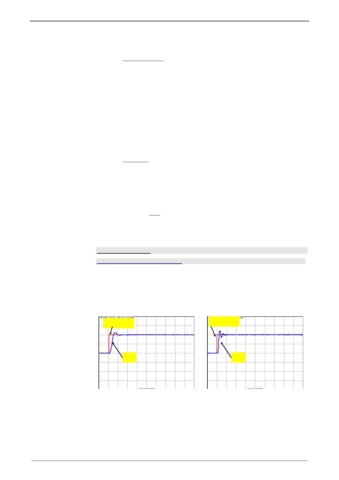
Current jerk response
Current jerk response of a motor to 2 different currents (1Arms / 2Arms)
2) (1Aeff)
1) 1)
2) (2Aeff)
1) Actual current
2) Setpoint current
In the above figure we can see from the settling response that the drive shows a
distinctive tendency to oscillate at doubled current. The saturation characteristic
line, which is used to linearly reduce the P-term of the current loop depending on
the current, helps against such a saturation behavior.
If you respect the saturation for the above example with the aid of the saturation
characteristic line, the tendency to oscillate of the current loop can again be activa-
ted.
Note:
 Loading...


