Parker EME
Compax3 device description
192-120114 N5 C3I22T11 June 2008 63
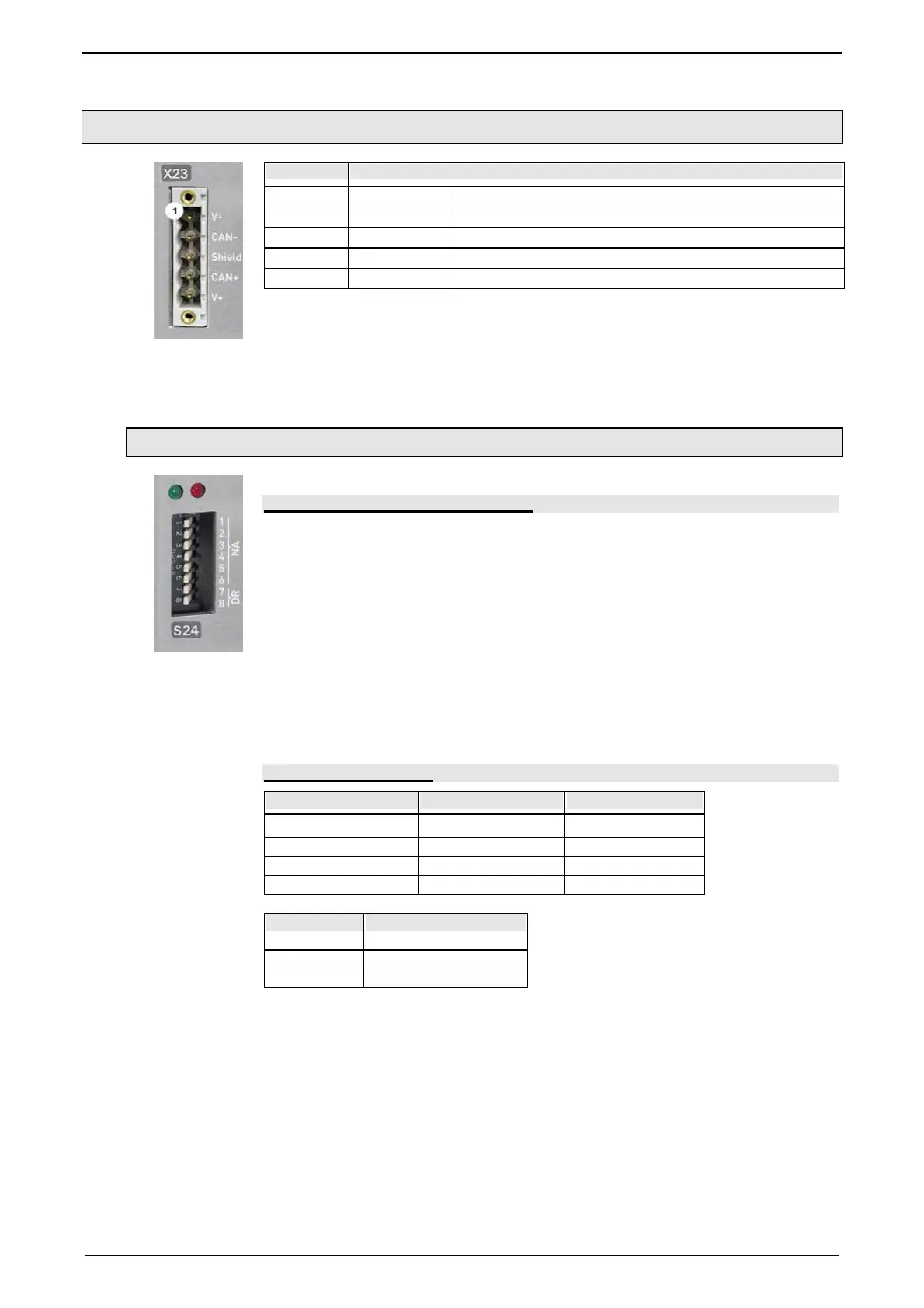
3.7.3. DeviceNet connector X23
Pin X23 DeviceNet (Open Plug Phoenix MSTB 2.5/5-GF5.08 ABGY AU)
1 V- Mass
2 CAN- CAN Low
3 Shield Shield
4 CAN+ CAN High
5 V+ not required, internal supply
A mating plug is included in the delivery.
If Compax3 is used as first or last device in the fieldbus network, a terminal resi-
stance of 121 Ω is required. This is integrated between Pin 2 and Pin 4.
Additional information on the DeviceNet wiring can be found under www.odva.org
http://www.odva.org.
Please d
o also heed the instructions in the DeviceNet master manual.
3.7.3.1 Adjusting the bus address
Address setting (NA: Node Address)
Values:
1: 2
0
; 2: 2
1
; 3: 2
2
; ... 6: 2
5
reserved
Settings:
left: OFF
right: ON
(The address is set to 2 in the illustration)
Range of values: 1 ... 63
Address 0 is set internally to address 63.
Data Rate setting (DR):
Data Rate [kBit/s] S24_7 S24_8
125 left: OFF left: OFF
250 left: ON right: OFF
500 right: OFF left: ON
Reserved right: ON right: ON
Bear in mind that the maximum cable length depends on the Data rate:
Data Rate Maximum length
500kbit/s 100m
250kbit/s 250m
125kbit/s 500m
 Loading...


