Setting up Compax3 C3I22T11
222 192-120114 N5 C3I22T11 June 2008
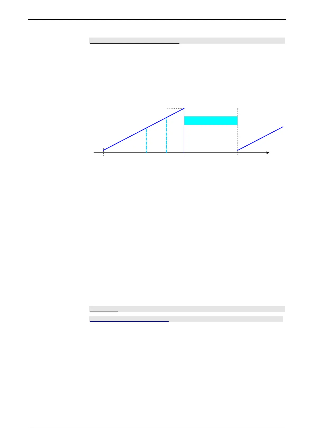
Test for positive feedback (phase 3)
Here it is verified, if the motor performs a motion in the expected positive direction
in the event of positive current in the torque maximum. The same motion threshold
(defined via O2190.3) as in phase 1 is valid. The test is repeated several times.
A current course in ramp form is specified (target: minimum movement). The break
between the tests varies witht he current rise time O2191.1.
Illustration of the third phase
t
t1
t
I
max
t1+t
test
max
t
=f(O2190.1)
1
1): Waiting for standstill
tp Waiting for standstill
Other
During the sequence (time according to parameterization>>1s) the automatic
commutation is externally visualized by a LED blinking code (green permanent
and red blinking).
Device errors will lead to an abort of the automatic commutation.
During automatic commutation, no motion commands are accepted.
The controller cascade entirely deactivated during automatic commutation, with
the exception of the current loop.
In multi-axis applications, the axes to be automatically commutated must be awai-
ted (output of the MC_Power block must deliver "True")!
The automatic commutation is only started if the drive is at standstill.
After the occurring and achnowledgement of a feedback error or a configuration
change of the feedback system, the automatic commutation must be performed
again, as it might be that the position entrainment in the servo controller is inter-
rupted (commutation information is lost).
Notch filter
In this chapter you can read about:
Effect of the notch filter .................................................................................................... 223
Wrongly set notch filter .................................................................................................... 223
Frequency response of the notch f
ilter. ........................................................................... 223
Parameterization by 3 objects. ........................................................................................ 223
Notch filters are small-band band elimination filters which slope in a wedge form
towards the center frequency. The attenuation of this center frequency is extremely
high in most cases. With the aid of the notch filters it is possible to purposefully
eliminate the effects of mechanical resonance frequencies. With this, the mechani-
cal resonance point is not activated itself, but the excitation of this point of reso-
nance is avoided by the control.
 Loading...


