Parker EME
Setting up Compax3
192-120114 N5 C3I22T11 June 2008 193
Velocity, bandwidth
In this chapter you can read about:
P-TE - Symbol ................................................................................................................. 193
Jerk response of a dela
y component............................................................................... 193
Approximation of a well-attenuated control loop.............................................................. 193
Frequency response of the P-TE
component (value and phase) .................................... 195
A well attenuated control loop can, under certain conditions, be approximated in
order to simplify the controller design with a first order delay component (P-TE
component) with the replacement time constant TE and the total gain Kp. A P-TE
component represents a first order delay component and is a simple dynamic basic
component.
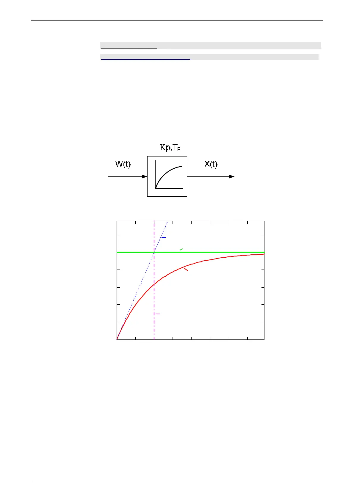
P-TE - Symbol
Jerk response of a delay component
Jerk response of a first order delay component with Kp=1 and TE=2.0s
01234567
0
0.2
0.4
0.6
0.8
1
1.2
XtTE,()
t
T
S
T
E
P-T
E
T: Tangent
S: Input jerk
P-TE: Output value of the P-TE component
TE: Time constant of the P-TE component
The definition of the delay time constant is displayed in the above figure. The time
of intersection of the tangent and the jerk function itself is by definition the delay
time constant (called filter time constant for filters) of a P-TE component. At this
point in time the value of the jerk response is approx. 63% of the final value. In
practice the jerk response corresponds, for instance, to the voltage charge curve of
a capacitor.
Approximation of a well-attenuated control loop
The approximation of a well-attenuated control loop is based on the sameness of
the control surface of the ideal first order delay component (P-T1 component) and
the approximated system (P-TE component).
The control surface is a measure for the velocity of a system and is defined in the
following figure. If the surface of the approximated system corresponds to the sur-
 Loading...


