Parker EME
Setting up Compax3
192-120114 N5 C3I22T11 June 2008 183
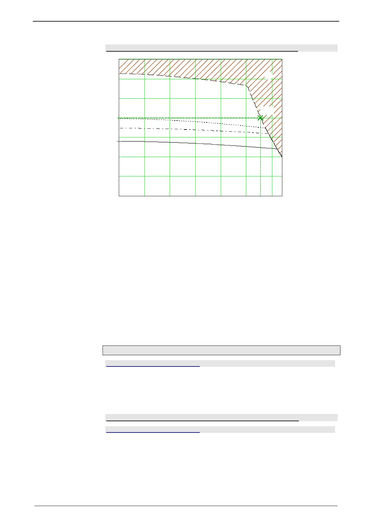
Reference point 2: Increased torque thanks to additional cooling
0 500 1000 1500 2000 2500 3000
0
0.5
1
2
2.5
3
3.5
S1 65°C DT
S3 50% 65°C DT
S3 20% 65°C DT
S1 105°C DT
[A]
[1/min]
22
I
0
n
2
I
2
rp2
I
0
Continual stall current
1: Nominal point
rp2: Reference point 2 (defined in the C3 ServoManager)
I
2
: Reference current to reference point 2
n
2
: Reference velocity to reference point 2
2: Forbidden range
In order to monitor the continous usage, the velocity-idenpendent current limit I
2
is
used.
If a r.m.s. current over the valid straight flows continually in the motor, the I²t mo-
nitoring will issue the "effective motor current monitoring" error message [0x5F48].
The period of time until the error occurs depends on the thermal time constant of
the motor defined in the motor parameters. The electronic temperature monitoring
simulates approximately the temperature behavior of the motor. By defining a refe-
rence point different from the motor nominal data, the I²t monitoring of the motor
can be adapted to changed thermal ambient conditions (e.g. air stream caused aby
a ventilator fan).
Relevant appication parameters
In this chapter you can read about:
Switching frequency of the motor current / motor reference point ................................... 183
External Moment of Inertia............................................................................................... 186
Limit and Monitoring Settings .......................................................................................... 187
Application parameters relevant for the control (C3 ServoManager)
Compax3 is configured with the aid of the C3 ServoManager. Here you can make
application dependant settings. Among these are also parameters, that are rele-
vant for the control. They will be explained below.
Switching frequency of the motor current / motor reference point
In this chapter you can read about:
Following Error (Position Error) ....................................................................................... 184
Reduction of the current ripple......................................................................................... 184
Motor parameters ............................................................................................................ 185
Changing the switching frequency
and the reference point............................................. 186
The higher the switching frequency, the better the quality of the current control. The
higher switching frequency reduces the dead time of the current control path as
well as the current control noise. Furthermore, thermal losses caused by current
ripple are reduced at higher switching frequencies.
 Loading...


