SmartPAC 2 User Manual 1126700
Installation 2-13
Table 2-1. Resolver Wiring
PIN # on TB101 Wire Color
Shield
(terminate to ground stud
nearest entry to enclosure)
212 (GND) No connection
213 (S1) Black*
214 (S2) Green
215 (R1) Red
216 (S3) Yellow*
217 (R2) Orange
218 (S4) Brown
* Shown for clockwise rotation, facing shaft.
For counterclockwise rotation, swap black and yellow wires.
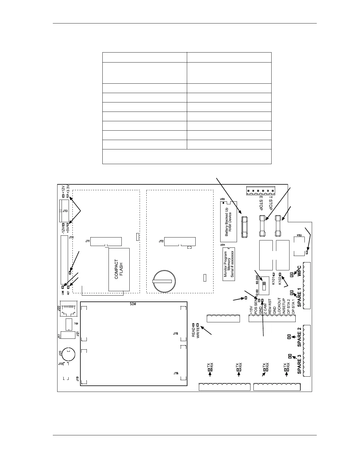
Figure 2-7. SmartPAC 2 Board: Location of Components
TB101
RESOLVER
S101
TB105
TB106
TB102
TB107
TB104 TB103
AUX I/O
AB
JP101
MASTER
SLAVE
JP102
SPEED
LOW
HIGH
INPUT
CHECK
SWITCH
11
1
1
1
1
1
ProCam DiPro
PACNET
SPECIAL MODULE
SFI
E-STOP
RELAYS
POSITION
SENSOR
LED
TX
RX
TX
RX
TX
RX
TX
RX
USB PORT
LEDS
TOP
STOP
LED
POWER
LEDS
ETHERNET
ETHERNET LEDS
LINK
ACTIVITY
USB
INPUT
CHECK
LED
E-STOP
LEDS
COMPACT
FLASH
ACCESS LED
K101 K102
F101
F102 F103
INPUT CHECK
FUSE
E-STOP
FUSE
TOP STOP
FUSE
TOP
STOP
RELAY
PS/2
ZERO
CAM
LED
+
BATTERY
 Loading...