SmartPAC 2 User Manual 1126700
Installation 2-15
(white) and ground (green). For 230 Vac, wires are black and red with green or green/
yellow for ground.
3. Connect the AC input wires and ground wire as shown in Figure 2-8 and Figure 4 at the
back of the manual. Make your ground connection as follows:
• SmartPAC 2 Enclosure: Connect your ground (green or green/yellow) wire to the set
screw terminal on the inside of the enclosure. To connect to the set screw terminal, strip
the ground wire about 1/4 in. (6.4 mm) from end, loosen the screw on the terminal, slide
the wire in the hole, and tighten the screw to secure the wire in place.
• SmartPAC 2 Panel Mount: Connect the ground wire to the ground stud on the face
plate below the AC input terminal block.
4. Connect AC wires to the power source only after all installation procedures have been
completed and you are ready to perform final checkout tests (see page 2-41).
Connecting Stop Circuits and Input Check Circuit
You need four wires to connect SmartPAC 2 to your press control stop circuits, two for the
emergency-stop circuit and two for the top-stop circuit. You can wire these circuits at your
press control. Refer to your press control manual or other electrical prints.
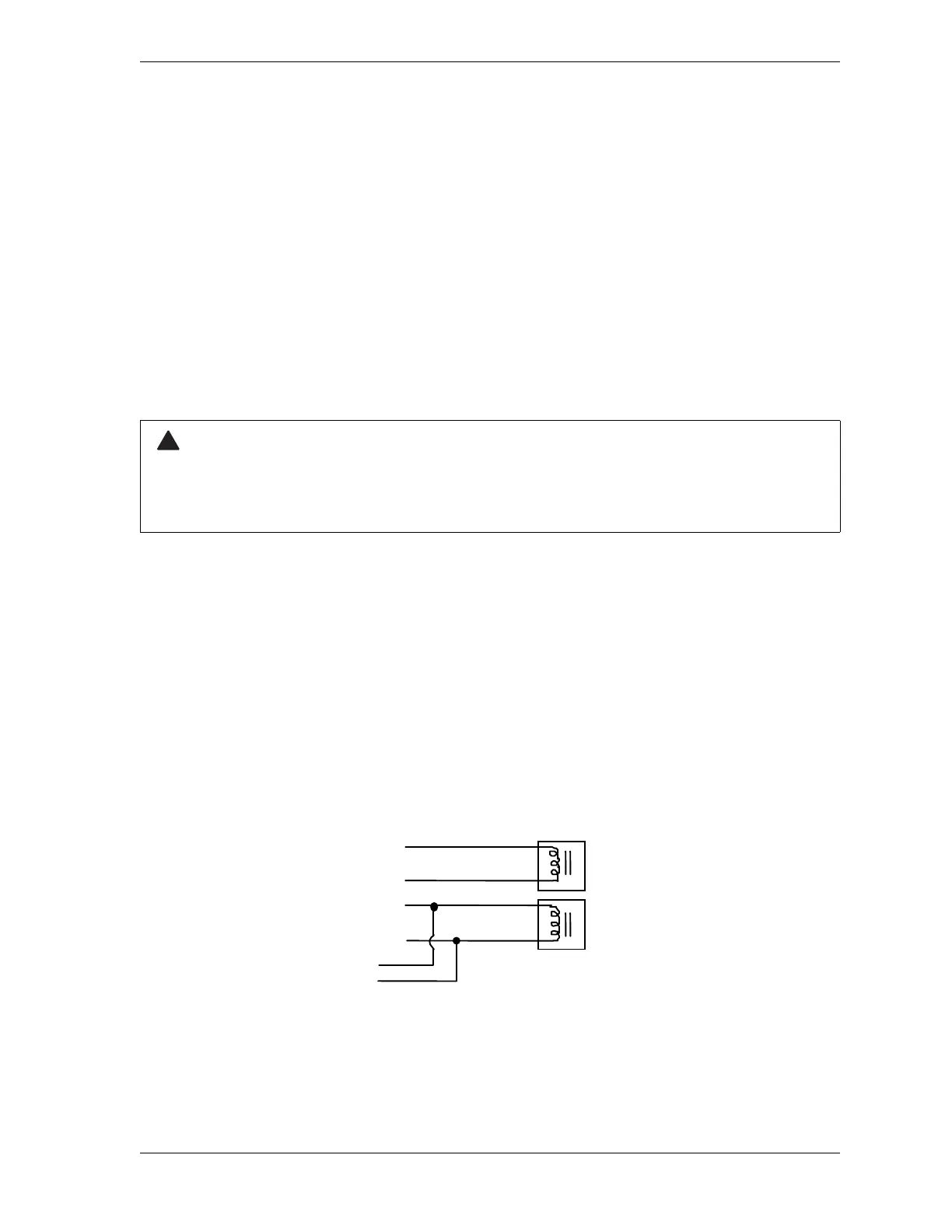
You need two wires to connect to the input check circuit. These wires are connected in
parallel with one of the coils on the Dual Safety Valve that controls the clutch/brake. When
the clutch is engaged, 12–250 Vac or Vdc (50-60 Hz) must be present across terminals A and
B, as shown in Figure 2-9. The connection can be made inside the press control where the
circuits to the valve relays are connected. Refer to your press control manual and electrical
prints. It does not matter which wire goes to terminal A and which to terminal B.
ELECTRIC SHOCK HAZARD
Do not connect the AC power source until you are done with all other installation procedures.
Failure to comply with these instructions could result in death or serious injury.
Figure 2-9. Schematic of Input Check Circuit for 10-130 Vac or Vdc
 Loading...