Page 7.1 - 22 COMBIVERT F5-A, -E, -H © KEB, 2012-10
Operating and appliance data
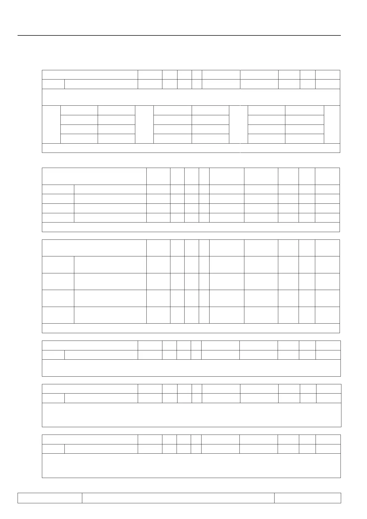
Parameter Addr. R PG E Min. value Max. value Res. [?] Default
Sy.11 Baudrate int. Bus 000Bh RW - + 3 11 1 - 11
The transmission rate between operator/inverter or PC/inverter is determined with the internal baudrate.
Following values are possible:
Value Baud rate Value Baud rate Value Baud rate
3 9.6 kBaud 6 55.5 kBaud 9 115.2 kBaud
4 19.2 kBaud 7 57.6 kBaud 10 125 kBaud
5 38.4 kBaud 8 100 kBaud 11 250 kBaud
After Power-On it is always started with 38.4 kBaud and dependent on the operator higher set.
Parameter Addr. R PG E Min. value Max.
value
Res. [?] Default
Sy.17 Proc. read data 1 set 0011h * - + 1 128 1 hex 1
SY.19 Proc. read data 2 set 0013h * - + 1 128 1 hex 1
SY.21 Proc. read data 3 set 0015h * - + 1 128 1 hex 1
Sy.17 Proc. read data 4 set 0016h * - + 1 128 1 hex 1
* rw via bus; r via keyboard
Parameter Addr. R PG E Min. value Max.
value
Res. [?] Default
SY.16 Proc. read data 1 de-
nition
0010h * - + -1 7FFFh 1 hex -1
SY.18 Proc. read data 2 de-
nition
0012h * - + -1 7FFFh 1 hex -1
SY.20 Proc. read data 3 de-
nition
0014h * - + -1 7FFFh 1 hex -1
SY.22 Proc. read data 4 de-
nition
0016h * - + -1 7FFFh 1 hex -1
* rw via bus; r via keyboard
Parameter Addr. R PG E Min. value Max. value Res. [?] Default
SY.32 Scope timer 0020h RO - - 0 65535 1 - 0
The scope timer generates a time period of 1 ms. This can be used by external programs, e.g. scope, to re-
present time patterns. The timer counts from 0...65535 and starts again with 0 after an overow.
Parameter Addr. R PG E Min. value Max. value Res. [?] Default
SY.41 Control word high 0029h RW - + 0 65535 1 - 0
The control word is used for state control of the inverter via bus. The control word long (Sy.43) consists of the
two 16 bit parameters control word high (Sy.41) and control word low (Sy.50). The status word is bit-coded.
The description of the individual bits is found in chapter 10.1.
Parameter Addr. R PG E Min. value Max. value Res. [?] Default
SY.42 Status word high 002Ah RO - - 0 65535 1 - 0
With the status word the current condition of the inverter can be readout via bus. The status word long (Sy.44)
consists of the two 16 bit parameters status word high (Sy.42) and status word low (Sy.51). The status word
is bit-coded. The description of the individual bits is found in chapter 10.1.
 Loading...


