Appendices
A - 18
Vision System FH/FHV/FZ5 Series User’s Manual (Z365)
Color changes within the measurement region are used to find defects such as scratches,contamina-
tion, and chipping.
After measurement region is drawn, a rectangle (defect detection region) is automatically formed in this
region. While moving the defect detection region around, calculate average density for each area to
determine the difference between the original area and the surrounding area. This difference is called
the defect level. Calculate the defect level for all defect detection areas. If the maximum value exceeds
the judgement value, it is judged that there are defects in the measurement region.
Increasing "Defect size" allows for shortening of processing time, but this will reduce measurement
accuracy.
A-5-4 Defect Detection Measurement
Setting item Description
Upper
Lower
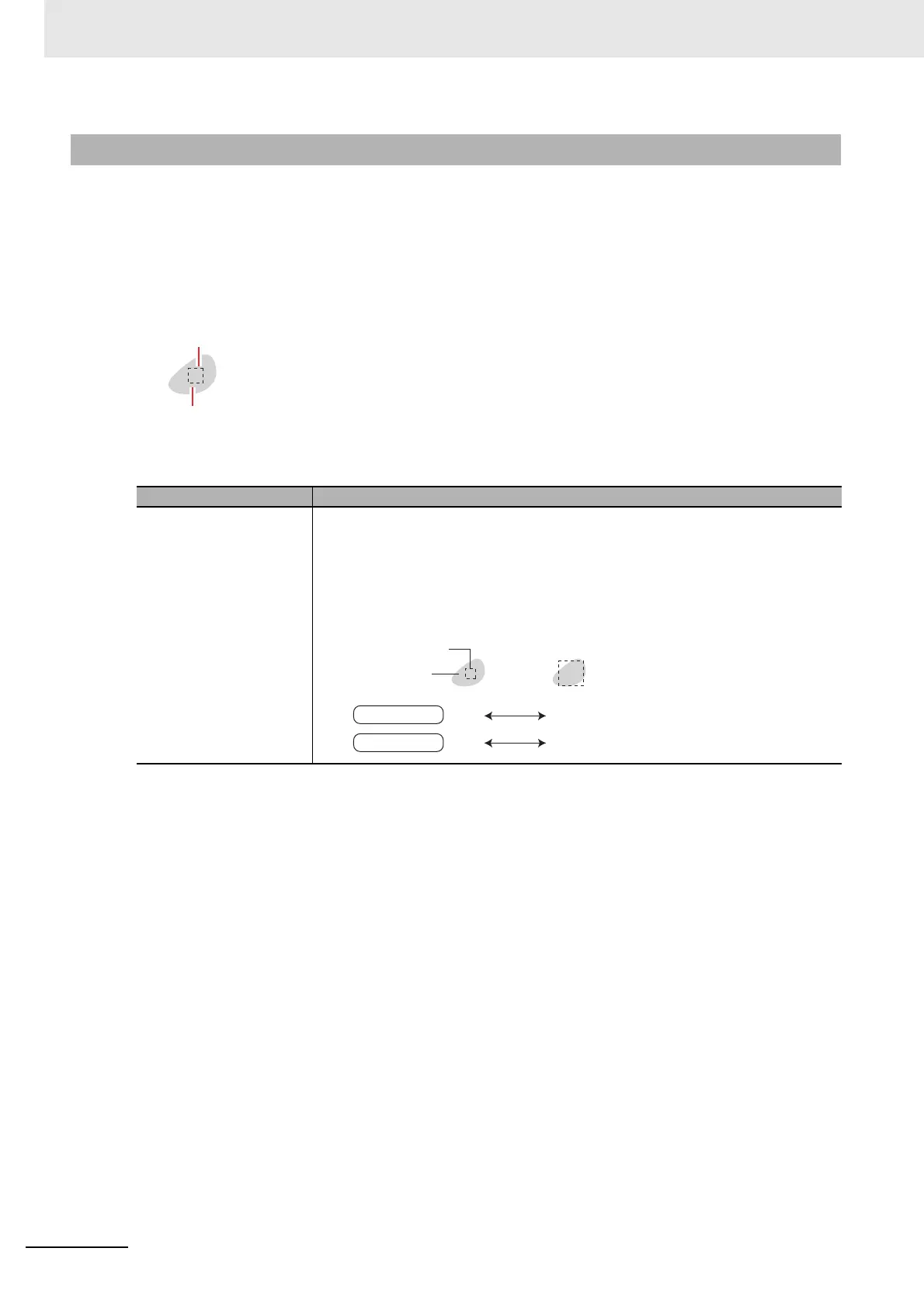
Specify the upper and lower limits of defect detection size based on the size of
scratch or contamination to be detected.
The larger the difference between upper and lower limits, the easier it is to detect the
scratches or contamination of various sizes.
For both upper and lower limits, higher values for defect detection size limits leads to
weaker detection sensitivity and shorter processing time.
Defect detection size
Defect
Sensitivity high low
Defect detection size
Defects
Processing time
long short

 Loading...

