3 Basic Operations
3 - 4
Vision System FH/FHV/FZ5 Series User’s Manual (Z365)
• When connecting cameras with two-cable connection, use a pair of ascending consecutive
even and odd numbered Sensor Controller camera connector numbers for each camera. You
will not be able to get the image acquisitions correctly if you use camera connectors with
non-consecutive connector numbers, or if an odd numbered connector has a lower number
than the even numbered connector it is paired with.
• CameraLink medium configuration is only supported by FH series Sensor Controller.
• When [Operation mode setting] has been set to the multi-line random trigger mode, changing
the camera connections or [Multi-line Random-trigger mode] in the system settings may
change camera number assignments in line with the change made. After changing the cam-
era connections or [Multi-line Random-trigger mode], before using the Sensor Controller,
check the camera numbers in the property setting screen for the [Camera Image Input] pro-
cessing items or [Camera Image Input FH] processing items.
• STGOUT signals (STGOUT0 to STGOUT7) signals are tied to the camera connector num-
bers, not the camera numbers. When using CameraLink Medium Configuration or Multi-line
Random-trigger mode, check the camera connector number of a Sensor Controller that cor-
responds to the camera number.
• SHTOUT signal (SHTOUT0 to SHTOUT7) are tied to the Line number, not camera number.
When use Multi-line random-trigger mode, confirm the Line number and use SHTOUT signal.
When connecting cameras with two-cable connection, the camera connection screen in the
system settings displays the camera model for one member of the pair of camera connector
numbers, and displays [Disconnect] for the other.
FH series/FZ5 series Sensor Controllers support the CameraLink standard’s Base Configuration. In the
base configuration, one camera cable is used to connect one camera. Starting from camera connector
0 on the Sensor Controller, connect cameras to the camera connectors you want to use in ascending
order of camera connector number.
No special preparations are required with this Controller because processing items are pre-installed.
Please check that the Controller is turned On and that the Main Window is displayed.
For details, refer to the Vision System FH/FZ5 series Hardware Setup Manual (Cat. No. Z366)/FHV
Series Smart Camera Setup Manual (Z408).
The first time the program is started, the Language Setting Dialog Box is displayed. Select the lan-
guage.
Refer to 4-1 Selecting Language [Startup Settings] on page 4-2.
6 --- 2
---
2
---
1
7 --- 3
One-cable Camera Connection
3-1-2 Preparing a Controller
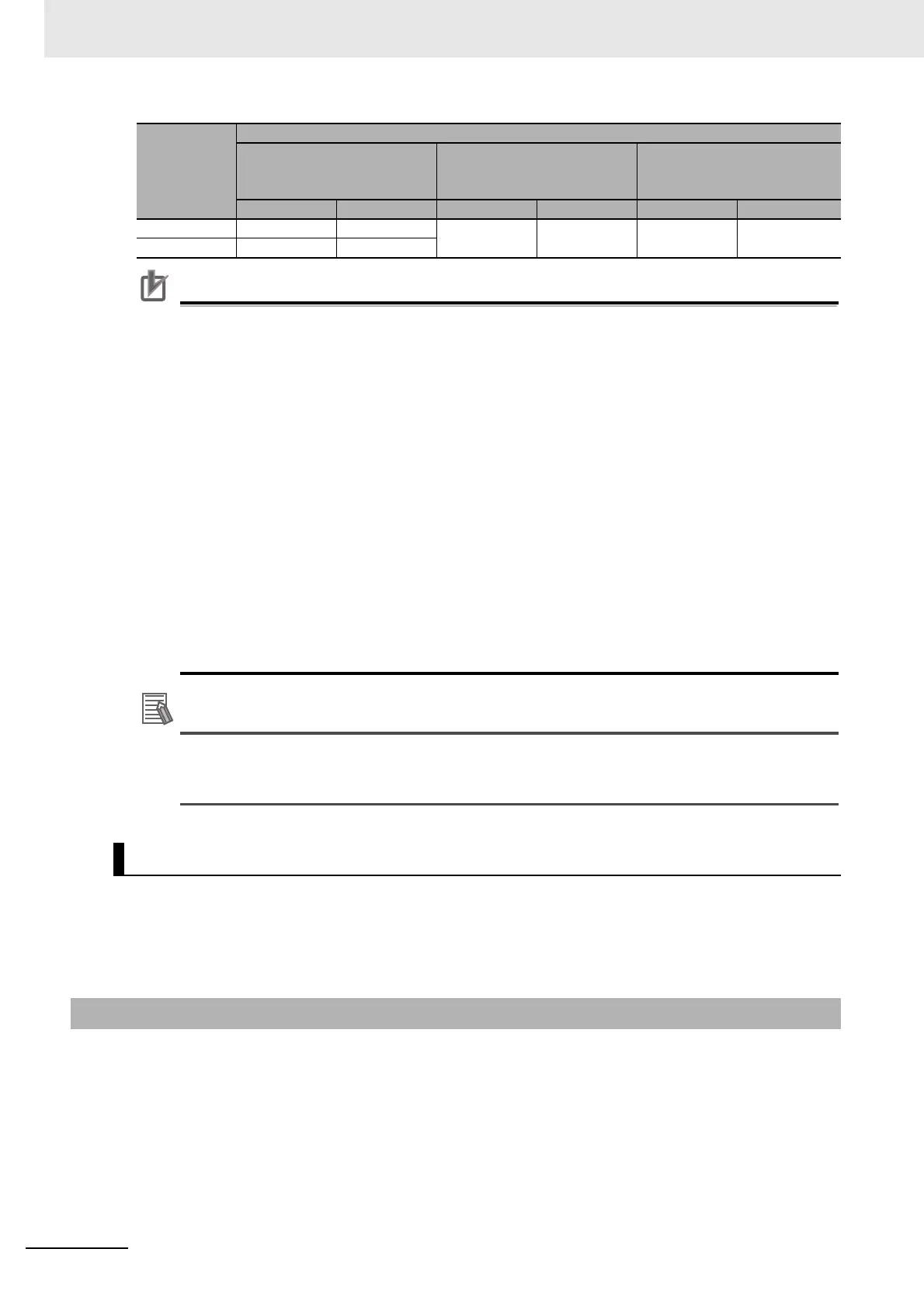
Sensor Con-
troller cam-
era
connector
number
Camera number in application software
Example when all cameras
use one-cable connection
Example when all cameras
use two-cable connection
Example when combining
one- and two-cable connec-
tion
Line 0 Line 1 Line 0 Line 1 Line 0 Line 1

 Loading...

