xStack® DGS-3620 Series Managed Switch Web UI Reference Guide
445
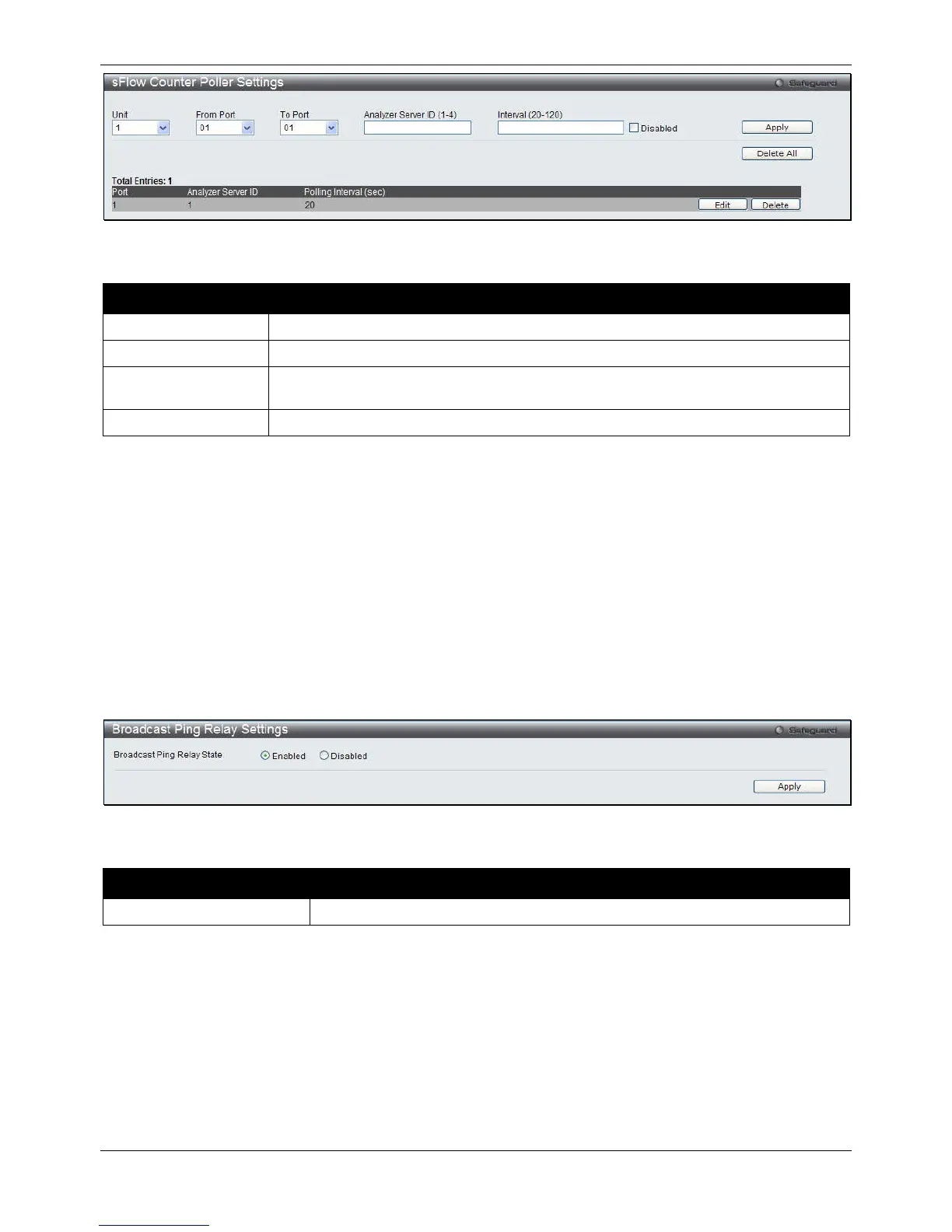
Figure 11-23 sFlow Counter Poller Settings
The fields that can be configured are described below:
Parameter Description
Select a unit to configure.
Use the drop-down menus to specify the list of ports to be configured.
Analyzer Server ID
The analyzer server ID specifies the ID of a server analyzer where the packet will be
The maximum number of seconds between successive samples of the counters.
Click the Apply button to accept the changes made.
Click the Delete All button to remove all the entries listed.
Click the Edit button to re-configure the specific entry.
Click the Delete button to remove the specific entry.
Ping
Broadcast Ping Relay Settings
This window is used to enable or disable broadcast ping reply state, device will reply broadcast ping request.
To view this window, click Monitoring > Ping > Broadcast Ping Relay Settings as shown below:
Figure 11-24 Broadcast Ping Relay Settings window
The fields that can be configured are described below:
Parameter Description
Broadcast Ping Relay State
Click the radio buttons to enable or disable broadcast ping relay state.
Click the Apply button to accept the changes made.
Ping Test
Ping is a small program that sends ICMP Echo packets to the IP address you specify. The destination node then
responds to or “echoes” the packets sent from the Switch. This is very useful to verify connectivity between the
Switch and other nodes on the network.
To view this window, click Monitoring > Ping > Ping Test as shown below:
 Loading...