OPERATING CONTROLS AND FEATURES GRT9165 OPERATOR MANUAL
3-28 Published 7-23-2020, Control # 668-02
Push and hold front of switch to tilt the cab up. Push and hold
rear of switch to tilt the cab down. Release switch when cab
is tilted to the desired position.
When cab is tilted up, the Cab Not Fully Lowered Indicator in
the Alerts Area (1, Figure 4-74) of the Operating Display
Module (ODM) comes on.
NOTE: Cab must be in the fully lowered position for the
drive functions to be enabled.
Swing Enable/Disable Switch
The Swing Enable/Disable Switch (16, Figure 3-17) is a
momentary switch that is located on the left armrest.
Press switch one time to enable the swing function. Press
switch another time to disable the swing function.
The Swing Enable/Disable Indicator in the Status Bar area
(6, Figure 4-74) of the Operating Display Module (ODM)
comes on (green) when the swing function is enabled. The
indicator goes off when the swing function is disabled.
Enabling one craning function (hoist, lift, telescope, or swing)
using its related Enable/Disable Switch will cause the engine
speed to increase to 1200 rpm. Disabling all craning
functions will cause the engine speed to decrease to
750 rpm.
Outrigger Extend/Retract Switch
The Outrigger Extend/Retract Switch (17, Figure 3-17) is a
three-position momentary switch that is located in the left
armrest.
Use Outrigger Extend/Retract Switch in combination with the
buttons on the Jog Dial or Navigation Control Pad, and the
Outrigger Extend/Retract Function Screen on the Operator
Display Module (ODM) to extend and retract the outrigger
beams and jacks.
Refer to Outrigger Extend/Retract, page 4-100 for complete
procedures on extending and retracting the outriggers.
NOTE: Push and hold the Outrigger Extend/Retract Switch
to quickly change the ODM screen display to the
Outrigger Extend/Retract Function Screen.
NOTE: Transmission Shift Lever must be in Neutral (center
position) and parking brake must be applied before
the outrigger controls will operate.
Differential Lock Switch
The Differential Lock Switch (18, Figure 3-17) is a
two-position momentary switch that is located on the left
armrest.
Use Differential Lock Switch to engage the differential lock
for additional traction. The Differential Lock can be activated
for a maximum of 60 seconds at a time.
NOTE: Crane must be in Four-Wheel-Drive to engage the
Differential Lock (refer to Drive Axle Selector
Switch, page 3-7).
Push and hold the Differential Lock Switch to engage the
Differential Lock. Release the switch to disengage the
Differential Lock. Refer to Differential Lock Operation, page
4-19 for more information on how and when to engage the
differential lock.
The Differential Lock Indicator in the Alerts Area
(1, Figure 4-74) of the Operating Display Module (ODM)
comes on when the differential lock is engaged.
Rear Steer Switch
The Rear Steer Switch (19, Figure 3-17) is a three-position,
spring centered to off, rocker switch located on the left
armrest.
Use the Rear Steer Switch to turn the wheels on the rear
tandem axles.
The Rear Steer Switch will only operate if one of the following
conditions is met:
• Transmission is in two-wheel drive (high range) AND
first gear is selected
- or -
• Transmission is in four-wheel drive (low range)
Rear Steer Switch will not operate if transmission is in
two-wheel drive (high range) and second or third gear is
selected. If operator pushes the Rear Steer Switch while
transmission is in two-wheel drive (high range), and the
current gear selection is second or third gear. the
Direction/Gear Indicator in the Crane Information Area
(3, Figure 4-74) of the ODM will alternate flashing between
first gear (1) and the current gear (either 2 or 3).
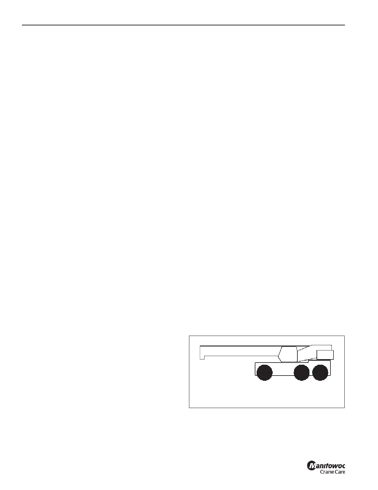
The GRT9165 crane can be driven in the Standard Driving
Configuration—with the boom centered over the front (single
axle). This Standard Driving Configuration is shown in
Figure 3-18.
The GRT9165 crane can also be driven in the Alternate
Driving Configuration—with the boom centered over the rear
FIGURE 3-18
Standard Driving Configuration
9898-1

 Loading...


