OPERATING PROCEDURES GRT9165 OPERATOR MANUAL
4-90 Published 7-23-2020, Control # 668-02
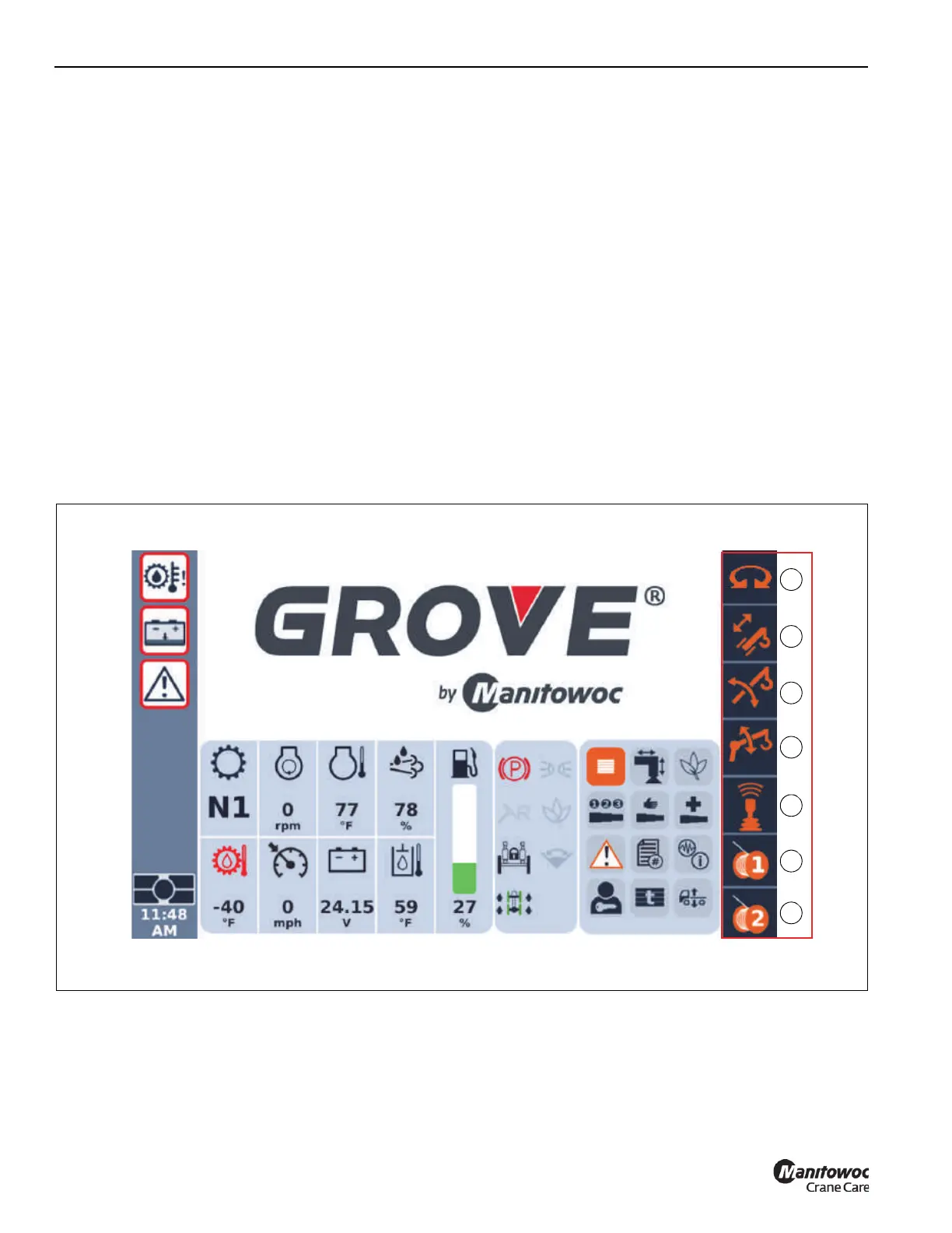
Status Bar
The indicators in the Status Bar (Figure 4-80) represent the
crane functions that are operated by the controllers on the
armrests.
Crane functions are enabled and disabled by Enable/Disable
Switches. As the status of a crane function changes (from
disabled to enabled, or back), its related indicator on the
Status Bar will change color.
The crane function indicators that show in the Status Bar
(Figure 4-80) include the following:
1. Swing (1)
2. Telescope (2)
3. Boom Lift (3)
4. Luffing Boom Extension (Optional) (4)
5. Remote Control Unit (5)
6. Main Hoist (6)
7. Auxiliary Hoist (7)
Each crane function indicator can have the following status:
• Blue Indicator – Indicates the crane function is disabled.
• Yellow Indicator (Constant On) – Indicates the crane
function is enabled, but is in a standby mode due to the
operator not being seated (causing seat switch to open –
refer to Seat Switch, page 3-32).
The crane function is re-enabled by either sitting in the
operator seat or by actuating a dead-man switch on the
left or right dual axis controllers [refer to Deadman
Switches (Optional) (Dual Axis), page 3-26].
• Yellow Indicator (Flashing) – Indicates the crane function
is being commanded [controller is moved out of neutral
(center) position] when the crane function is changed
from disabled to enabled.
Allow controller to return to its neutral position, then
re-enable the crane function.
• Green Indicator – Indicates the crane function is
enabled.
FIGURE 4-80
9902-1A
1
3
6
4
2
5
7

 Loading...


