Grove Published 7-23-2020, Control # 668-02 5-85
GRT9165 OPERATOR MANUAL SET-UP AND INSTALLATION
Removing the Lattice Insert from the Boom
Nose
Use the following procedure to remove the lattice insert from
the boom nose.
1. Use another auxiliary crane or suitable lifting device to
remove the extension.
2. Connect a sling to the lifting lugs and lift the extension
enough to take the load off the connecting pins. For
more information about attaching points, see Lifting
Points, page 5-50.
3. Verify the electrical and hydraulic connections are
disconnected. Refer to Boom Extension and Lattice
Insert Electrical Connections, page 5-72 and Hydraulic
Boom Extension Connections, page 5-73.
4. Remove the retaining clips and pins (4 and 5,
Figure 5-69) from the connecting points.
5. Insert the pins (4) into the holders. Secure pins (4) with
retaining clips (5).
6. Remove the lattice insert (2). Lower the lattice insert on
to a stable surface.
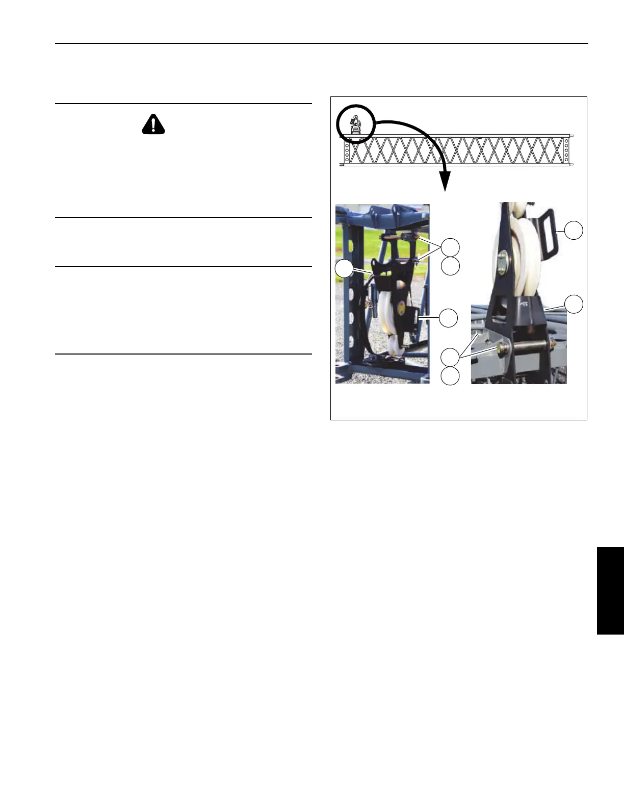
7. Lower the Lattice Insert mast sheave assembly as
follows:
a. Hold the handle (1, Figure 5-73) and remove
retaining clips (2) and pins (3).
b. Swing the mast sheave assembly (4) to the lowered
position. Align the holes.
c. Install pins (3). Secure with retaining clips (2).
Boom Extension-to-Lattice Insert Hydraulic
Connections
Use the following procedures to connect the optional
hydraulic boom extension to the lattice insert.
DANGER
Boom Extension Hazard!
To avoid death or serious injury, follow procedures and
cautions in the Operator and Safety Manuals and decals
during erection, stowage and use of boom extension.
Install and secure all pins properly and control boom
extension movement at all times.
CAUTION
Equipment Damage Hazard!
Before removing an extension, ensure that the electrical
and hydraulic connections have been disconnected and
properly stowed to prevent damaging the rope and
hydraulic hoses.
1
1
2
3
4
4
2
3
Lowered
Raised
FIGURE 5-73
10016
10017
10018

 Loading...


