OPERATING PROCEDURES GRT9165 OPERATOR MANUAL
4-142 Published 7-23-2020, Control # 668-02
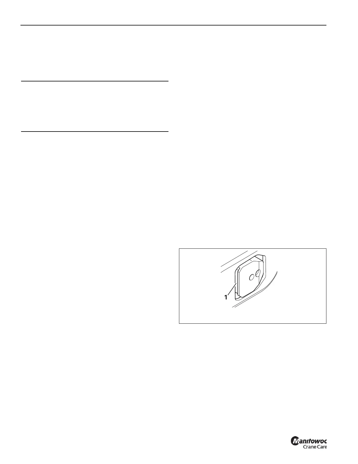
Extending and locking the telescoping cylinder
Under no circumstances should you select and press the
lock symbol (1, Figure 4-139) while the tele cylinder is in
motion.
Slowly move the telescoping cylinder into the next extended
telescopic section.
At the locking point:
• The display (2, Figure 4-135) shows the length for the
current locking point, refer to (Table 4-2)
• The proximity switch indicators for S2117N, S2118N,
and S2116N are used to align the tele cylinder to the
hole in the boom section. S2118N is on whenever the
tele cylinder pins are in the “foot section” or the near end
of the boom section weldment where the hole is located.
S2116N comes on when the tele cylinder has extended
beyond the hole. S2117N comes on when the tele
cylinder is not extended enough to reach the hole.
Therefore, one would operate the tele cylinder until
S2118N is on, and S2116N and S2117N are off. This is
what is shown in Figure 4-140.
• Select and confirm the symbol shown as Item 4 in
Figure 4-136.
The telescoping cylinder is locked if the actuator is able
to release the cylinder pins, and the tele cylinder is
actually aligned with a pinning location hole in the boom
section. The screen should appear as shown in
Figure 4-137.
• With the tele cylinder locked to the section, extend the
tele cylinder approximately 15mm to 30mm to clear the
cut out on the tele section locking pins (refer to Locking
points for the telescopic sections, page 4-142). You can
now unlock the tele section from its outer section, then
operate the telescopic cylinder. Refer to Retracting and
locking a telescopic section, page 4-140.
Tables for approaching the locking points
The extent to which the telescoping cylinder has to be
extended in order to reach a locking point depends on
whether you want to lock:
• the telescoping cylinder or
• a telescopic section.
Locking points for the telescoping cylinder
Table 4-2 shows the extended length for locking the
telescoping cylinder.
Locking points for the telescopic sections
Table 4-1 shows the extended length for locking the
telescopic boom sections together. Lengths for locking the
telescope boom sections at 50%, 55%, 92%, and 100% are
30 mm greater than those in Table 4-2.
This added length is needed for the tele section locking pins
to first clear the holes in the outer tele section. After the tele
section locking pins are extended and locked into the outer
holes, the tele cylinder is to be retracted 30 mm to set down
the tele section and bring the tele section locking pins into
contact with the bottom of the holes is the outer tele section
(1 .Figure 4-141).
CAUTION
Machine damage hazard!
If you select Lock while the telescoping cylinder is
moving, the locking pins on the telescopic section are slid
out immediately and they can damage or tear the
electrical or hydraulic components in the main boom.

 Loading...


