OPERATING PROCEDURES GRT9165 OPERATOR MANUAL
4-44 Published 7-23-2020, Control # 668-02
• The operator can continue to command the retract
direction and the second boom section to move will be
retracted. And, as before, it can be locked at its 0%
pinning location.
• Note that when the boom is fully retracted, the
telescoping cylinder does not automatically move to
another boom section (such as automatically moving to
the T1 boom section). The telescoping cylinder will
remain at the boom section that was the last to be
retracted. However, this cylinder can be moved to
another boom section with the Semi-auto Mode. Refer to
Semi-auto Mode for Shifting Cylinder within Fully
Retracted Boom, page 4-44 for shifting cylinder within a
fully retracted boom.
Semi-auto Mode for Shifting Cylinder within
Fully Retracted Boom
It may be desirable to have the telescoping cylinder locked to
a particular boom section while the boom is fully retracted.
The following procedure can be used:
• Enter the Semi-auto screen of the ODM.
• Verify that the telescoping function is enabled.
• Enter a requested final boom configuration with 0% for
each of the boom sections, EXCEPT for the boom
section where the tele cylinder is desired to be locked to.
For this one boom section, enter 50/55%. For example,
if the telescoping cylinder is desired to be locked to the
T1 boom section (and it is not located there currently),
then 55-0-0-0-0 would be entered.
• If the telescoping cylinder is not at the boom section
desired, it will shift to that boom section.
• When the telescoping cylinder is locked to the desired
boom section, that boom section will be automatically
unlocked (as if it is to be operated).
• Use the telescope controller to retract for at least 1
second. The boom section will re-lock, and the boom
should still be fully retracted and locked, and the
telescoping cylinder will be in the position desired (such
as locked to T1 boom section).
Semi-auto Mode Requiring Boom to be
Retracted
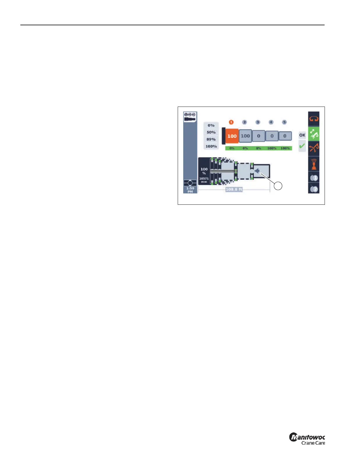
It is important to understand that a new requested final boom
configuration (“target tele picture”) may require the boom to
be retracted first. For example, if the requested final boom
configuration is currently 0-0-0-100-100, and the boom is
extended to this configuration, and then a new requested
final boom configuration (such as 100-100-0-0-0) is entered,
it is impossible to use the new configuration unless the
existing boom sections are retracted first. When this
condition arises, only the left telescoping direction arrow (1)
will be shown on the display (as seen in Figure 4-42). When
the boom is fully retracted, then the automated motions
should proceed to the new configuration. That is, for the
example, when T2 is locked at 0% (after using the joystick to
retract everything), then telescoping cylinder can move to
the T5 boom section to be unlocked (since it is the first boom
section to move for the new final boom configuration of
0-0-0-100-100).
Semi-auto Mode Screen Refresh
When the Semi-auto screen of the ODM is entered, the final
boom configuration (“target tele picture”) that is shown is the
one most recently ACCEPTED and is actually being used to
control/operate the boom. If the screen is exited and
re-entered, what is shown may not be the most recently
REQUESTED final boom configuration.
As noted in the section of the document 'Semi-auto Mode
Requiring Boom to be Retracted', there are cases where a
newly requested final boom configuration can not be
accepted until the current boom configuration is completed
to have the boom fully retracted. If the Semi-auto Mode is
currently requiring the boom to be retracted, and the ESC
button is used to leave the Semi-auto screen, and then
Semi-auto screen is entered again, the values shown for
boom sections will revert to the original boom configuration,
the ACCEPTED boom configuration (until the boom is fully
retracted and the control system can then “shift” to the new
REQUESTED final boom configuration).
Semi-auto Mode Warning Indications
The control system manages a fault indication system. This
is characterized by a set of error codes or fault codes. When
a fault condition is noted by the control system, the icon in
Figure 4-43 is seen in the Alerts Area (Figure 4-75) of the
ODM. There is also a screen of the operating display that
uses this icon, and that screen will show the fault codes.

 Loading...


