Grove Published 7-23-2020, Control # 668-02 5-67
GRT9165 OPERATOR MANUAL SET-UP AND INSTALLATION
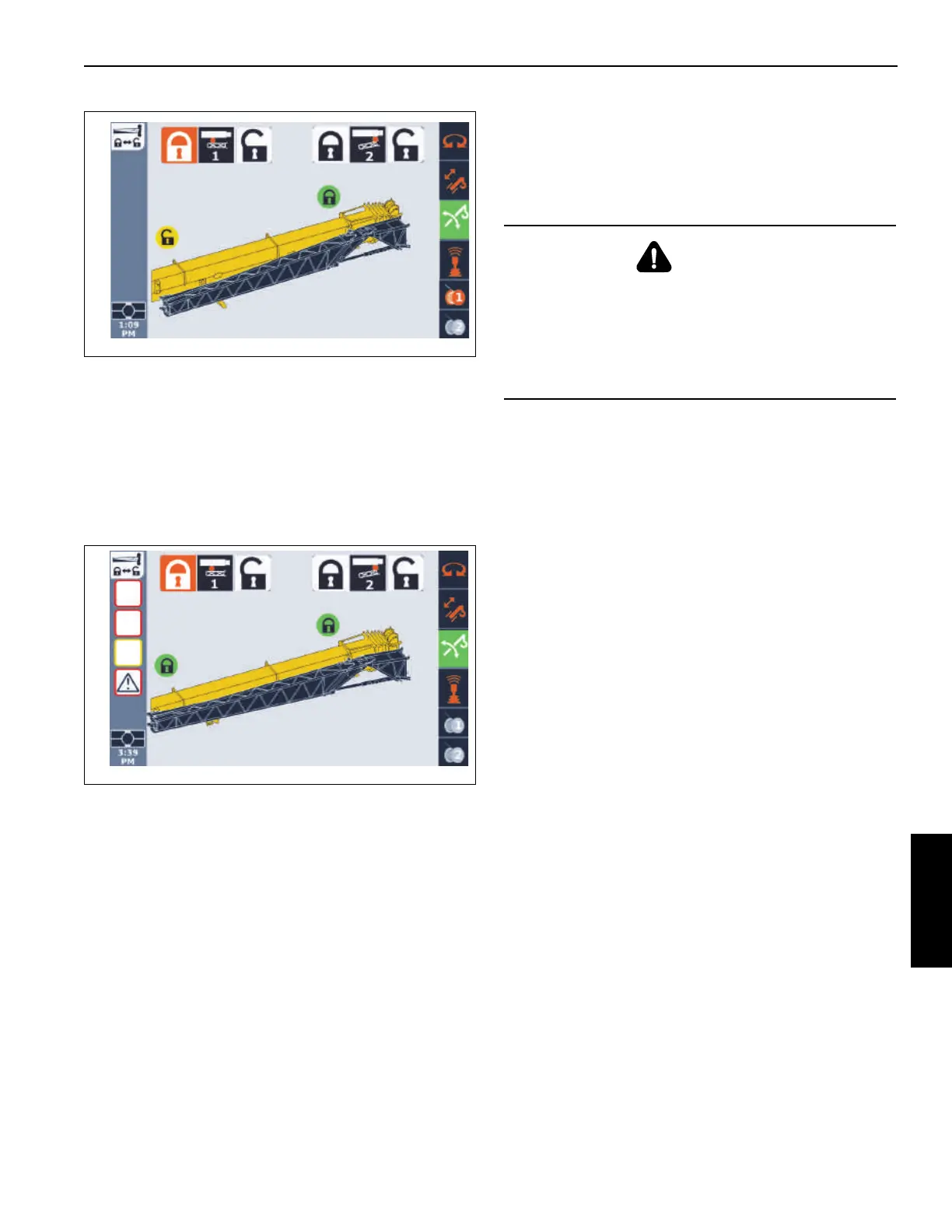
a. Use the ODM control pad arrow buttons or jog dial
to highlight lock icon.
The lock icon highlights (orange).
b. Press and hold the OK on the ODM control pad or
press down on the jog dial.
The lock status indicator icon turns green, indicating
the pin is extended. The boom extension is
displayed as secured to the main boom.
20. Visually verify that the rear mounting pin is securely
installed.
21. Unreeve and remove tag line (2, Figure 5-54).
22. Attach the fly section to the stowage bracket (3,
Figure 5-46) with pin (1) and retaining clip (2). Insert pin
(4) and secure with retaining clip (3).
23. Disconnect boom extension electrical connections. For
more information, see Boom Extension and Lattice
Insert Electrical Connections, page 5-72.
24. If stowing a hydraulic boom extension, disconnect
hydraulic hoses. For more information, see Hydraulic
Boom Extension Connections, page 5-73.
Erecting the 10.9 m Boom Extension Base
Section Only
Use the following procedure to erect the boom extension
base section. During this procedure, the boom extension
base section is decoupled from the fly section and attached
to the boom nose. The fly section remains attached to the
side of the main boom. In the ODM, Pin #1 will be shown as
locked.
NOTE: This procedure assumes the boom extension and
fly section are installed on the side of the main
boom.
1. Make sure the counterweight is installed. For more
information about installing the counterweight, see
Counterweight Removal and Installation, page 5-12.
1. Make sure the crane is set up on fully extended
outriggers. For more information, see Using the
Outriggers, page 4-21.
2. Retract and lower the boom to horizontal.
3. Connect boom extension electrical connectors. For
more information, see Boom Extension and Lattice
Insert Electrical Connections, page 5-72.
4. If erecting a hydraulic boom extension, connect
hydraulic hoses. For more information, see Hydraulic
Boom Extension Connections, page 5-73.
5. If erecting an optional hydraulic boom extension, make
sure the angle indicator (1, Figure 5-55) is aligned. If the
arrows are not aligned, adjust the boom extension offset
as needed to align the arrows. For more information, see
Setting the (Optional) Hydraulic Boom Extension Offset,
page 5-79.
DANGER
Boom Extension Hazard!
To avoid death or serious injury, follow procedures and
cautions in the Operator and Safety Manuals and decals
during erection, stowage and use of boom extension.
Install and secure all pins properly and control boom
extension movement at all times.

 Loading...


