Grove Published 7-23-2020, Control # 668-02 5-53
GRT9165 OPERATOR MANUAL SET-UP AND INSTALLATION
Accessing the Boom Extension Group in the
ODM
Use the following procedure to access the boom extension
group in the ODM. For more information about the ODM
navigation control pad or jog dial, see Navigating the
Operator Display Module and Rated Capacity Limiter Display
Module, page 4-71.
1. Access the Menu Screen.
2. Use the ODM navigation pad or jog dial to highlight the
Boom Extension Deployment/Stowage icon.
3. Press the OK button on the ODM navigation pad or
press down on the jog dial to select the Boom Extension
Deployment/Stowage icon.
The boom extension group screen appears.
Installing the Boom Extension
Use this procedure to install the boom extension base
section and fly section that are separate from the crane on to
the boom nose.
NOTE: This procedure assumes the boom extension is
completely removed from the boom nose and the
fly section is stowed on the boom extension base.
NOTE: This procedure applies to manual and hydraulic
boom extensions unless otherwise noted.
1. Make sure the counterweight is installed. For more
information about installing the counterweight, see
Counterweight Removal and Installation, page 5-12.
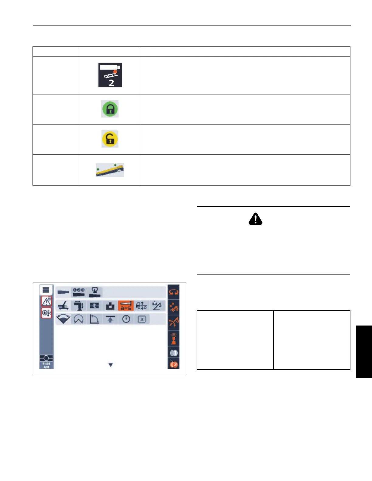
2 Front Boom Extension Mounting Pin (pin #2).
3 and 4 Boom Extension Rear or Front Mounting Pin Status: Locked
3 and 4 Boom Extension Rear or Front Mounting Pin Status: Unlocked.
5
Boom Extension status indicator. This icon changes depending on the location of
the boom extension.
Table 5-4 Boom Extension Group Icons (Continued)
Item(s) Icon Description
DANGER
Boom Extension Hazard!
To avoid death or serious injury, follow procedures and
cautions in the Operator and Safety Manuals and decals
during erection, stowage and use of boom extension.
Install and secure all pins properly and control boom
extension movement at all times.
Required Tools
• 1/2 in Impact Wrench
• 24in — 1/2in Drive
Impact Extension
• 1/2 in Square Drive
Socket — 14mm
impact rated hex
socket

 Loading...


