5-78 Published 7-23-2020, Control # 668-02
SET-UP AND INSTALLATION GRT9165 OPERATOR MANUAL
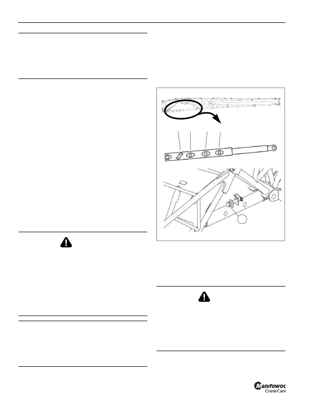
The boom extension can be set manually to the positions
shown in Figure 5-65.
Setting the Offset Angle Mechanically with an
Auxiliary Crane
If an auxiliary crane is available, the boom extension can be
attached to a sling to set the angle. If an auxiliary crane is not
available, refer to Setting the Offset Angle Mechanically
without an Auxiliary Crane, page 5-78.
1. Lift the boom extension with the auxiliary crane until the
pin is relieved of load. For more information about lifting
positions, see Lifting Points, page 5-50
2. Lift or lower the extension with the auxiliary crane until
the adjusting pin (1, Figure 5-65) can be installed into
the position for the required angle.
3. Lower the boom extension with the auxiliary crane and
remove the lifting gear.
Setting the Offset Angle Mechanically without an
Auxiliary Crane
If an auxiliary crane is not available, the extension head must
rest on the ground before the angle is changed.
Setting a Manual Offset Angle of 0°, 15°, 30°,
or 50°
This section assumes that the manual offset extension is
pinned on front of the main boom, the hook block or
downhaul weight are removed, and the unreeved rope is laid
beside the boom extension.
NOTE: No pin is required to set the 50° offset angle.
1. In the ODM, configure the crane for the offset angle to
be used. The options are 0°, 15°, 30°, or 50°.
2. Stow the boom extension mast sheave assemblies.
3. Extend the main boom as necessary, or as far as
possible given the space available.
CAUTION
Risk of Equipment Damage!
Always stow the mast sheave assemblies before
adjusting the boom extension offset angle.
This will prevent any interference between the mast
sheave assemblies and boom extension.
WARNING
Tipping Hazard!
Always enter the RCL rigging code for the current rigging
mode of the crane. Only rotate the superstructure into the
working position permitted by the RCL rigging code set
according to the Load Chart.
This prevents the crane from overturning when the main
boom is extended.
The telescoping range which is enabled for the rigging
code is only permissible for telescoping without a load
and without hook block/hook tackle.
CAUTION
Risk of Damage to the Wire Rope!
Unreeve the hook block and lay the hoist rope beside the
boom extension before you set the angle of the extension.
This prevents the rope from being damaged when the
head of the boom extension is set on the ground.
WARNING
Crushing Hazard!
If the extension is lowered onto timbers or some other
structure to set the angle, keep in mind that as the
extension is raised the extension head will slide towards
the crane until the set angle is reached.
The extension could slip off an unsuitable structure, fold
down and cause serous injury or death.
0°
15°
30°
50°
FIGURE 5-65
1
10007
10006
9992

 Loading...


