5-62 Published 7-23-2020, Control # 668-02
SET-UP AND INSTALLATION GRT9165 OPERATOR MANUAL
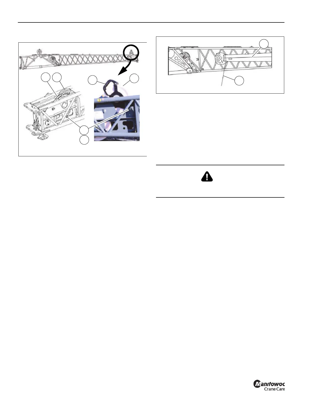
23. Raise the front mast assembly as follows:
a. Hold the handle (1, Figure 5-49) of the mast sheave
assembly (2). Remove retaining clip (3) and pin (4).
b. Raise the mast assembly (2) until the connecting
holes are aligned.
c. Insert pin (4) and secure with retaining clip (3).
24. Reeve the hoist rope. For more information, see
Reeving the Hoist Rope, page 5-77.
25. Remove the anti-two block switch from the main boom
nose. For more information, see Anti-Two Block (A2B)
Switch, page 5-32. Install the anti-two block switch. For
more information, Anti-Two Block (A2B) Switch, page
5-32.
26. (Optional) Install the anemometer and boom position
light. For more information, see Anemometer/Boom
Position Light (Optional), page 5-88.
Erecting the Fly Section
Use this procedure to deploy the boom extension fly section.
NOTE: This procedure assumes the boom extension is
erected and fly extension is folded on the boom
extension base section.
1. Make sure the locking bar (3, Figure 5-51) and pins can
retaining clips (9 and 10, Figure 5-52) are properly
installed.
2. Tie a tag line (1, Figure 5-50) to the end of the fly section
(2).
3. Remove the retaining clip (1, Figure 5-51) and pin (2)
from the boom extension fly section (4). Remove the
locking bar (3) from the boom extension fly section (4).
Rotate the locking bar (3) and store the clip and pin in
retaining bracket (5) on the boom extension base
section (6).
4. Remove the fly section electrical connection from fly
section stowage receptacle (1, Figure 5-52). Connect
the fly section electrical connector to the receptacle (2)
on the boom extension base section (3).
5. Remove the retaining clips (8) and pins (7) from stowage
bracket (11) as necessary. Using the tag line, swing the
fly section (4) around and engage the fly attachment
fittings (5) with the base section anchor fittings (6).
6. Install the pins (7) into the fittings (5 and 6). Secure the
pins with retaining clips (8).
7. (Optional) Install and connect the wind speed indicator
and boom position light assembly on the end of the fly
section. For more information, see Anemometer/Boom
Position Light (Optional), page 5-88.
8. Remove the tag line from the end of the fly section.
9. Reeve the hoist rope. For more information, see Hoist
Rope Reeving, page 5-34.
10. Remove the anti-two block switch from the main boom
nose. For more information, see Anti-Two Block (A2B)
Switch, page 5-32. Install the anti-two block switch on
the nose of the fly section. For more information, see
Anti-Two Block Switch on the Boom Extension, page
5-79.
Lowered Position Raised Position
FIGURE 5-49
1
1
2
3
4
2
9912
9913
10004
DANGER
When erecting the fly section, make sure that all
personnel and equipment are kept clear of the swing path.

 Loading...


