Grove Published 7-23-2020, Control # 668-02 4-107
GRT9165 OPERATOR MANUAL OPERATING PROCEDURES
3. Using the Jog Dial or the Arrow Buttons on the
Navigation Control Pad, select the Lock icon
(2, Figure 4-108).
4. Press the Jog Dial or the OK Button to start the locking
process.
When the lock is engaged, the Locked Status Indicator
(4, Figure 4-109) will appear.
Unlocking the Superstructure
1. Press and hold the swing brake pedal.
2. Using the Jog Dial or the Arrow Buttons on the
Navigation Control Pad, select the Unlock icon
(3, Figure 4-108).
3. Press the Jog Dial or the OK Button to start the locking
process.
When the lock is disengaged, the Unlock Status
Indicator (4, Figure 4-108) will appear.
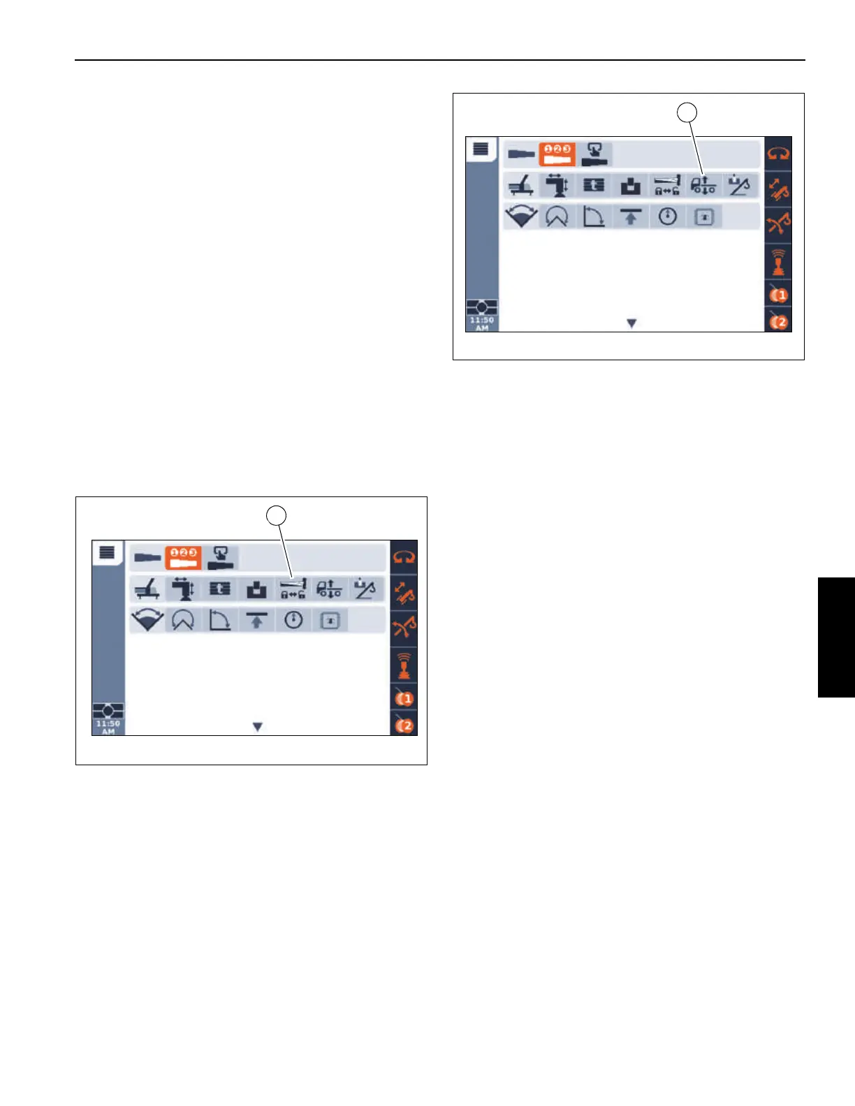
Boom Extension Deployment/Stowage
Select the Boom Extension Deployment/Stowage icon
(1, Figure 4-110) under the Crane Function Group to show
the Boom Extension Deployment/Stowage function screen.
The Boom Extension Deployment/Stowage function screen
is used to extend and retract the front and rear boom
extension pins that secure the boom extension to the boom
base section.
Complete procedures for the deployment and stowage of the
boom extension, including the use of the Boom Extension
Deployment/Stowage function screen, are found in
SECTION 5 - SET-UP AND INSTALLATION.
Suspension Raise/Lower
Select the Suspension Raise/Lower icon (1, Figure 4-111)
under the Crane Function Group to show the Suspension
Raise/Lower function screen.
The Suspension Raise/Lower function screen (Figure 4-112)
is used to lower and raise the crane suspension.
NOTE: When traveling the crane or performing a pick and
carry, the suspension must be at the Ride Height,
which is indicated by a green Suspension Ride
Height Status Indicator (7, Figure 4-112). Fully
raise the suspension when performing an
On-Rubber, Stationary, 360° lift. When the
suspension is not at the Ride Height, the
Suspension Ride Height Status Indicator is red
(5, Figure 4-112).
Before the suspension can be raised or lowered, the
following conditions must be met:
• Boom must be centered over the front or rear of the
carrier.
• Turntable Swing Lock Pin must be engaged.
• Rated Capacity Limiter (RCL) must be programmed with
a Travel load chart code number.
• Rear wheels must be centered.
Raise and lower the suspension by performing the following
procedures:
1. Using the Jog Dial or Arrow Buttons on the Navigation
Control Pad, select the Raise icon (1, Figure 4-112).
2. With focus on the Raise icon, press and hold the Jog
Dial or the OK button.
The left and right side suspension will begin to raise.
3. Release the Jog Dial or OK button when the Suspension
Ride Height Status Indicator (5, Figure 4-112) changes
from red to green, indicating the suspension is at the
Ride Height.
4. Using the Jog Dial or Arrow Buttons on the Navigation
Control Pad, select the Lower Suspension icon
(2, Figure 4-112).

 Loading...


