Grove Published 7-23-2020, Control # 668-02 5-51
GRT9165 OPERATOR MANUAL SET-UP AND INSTALLATION
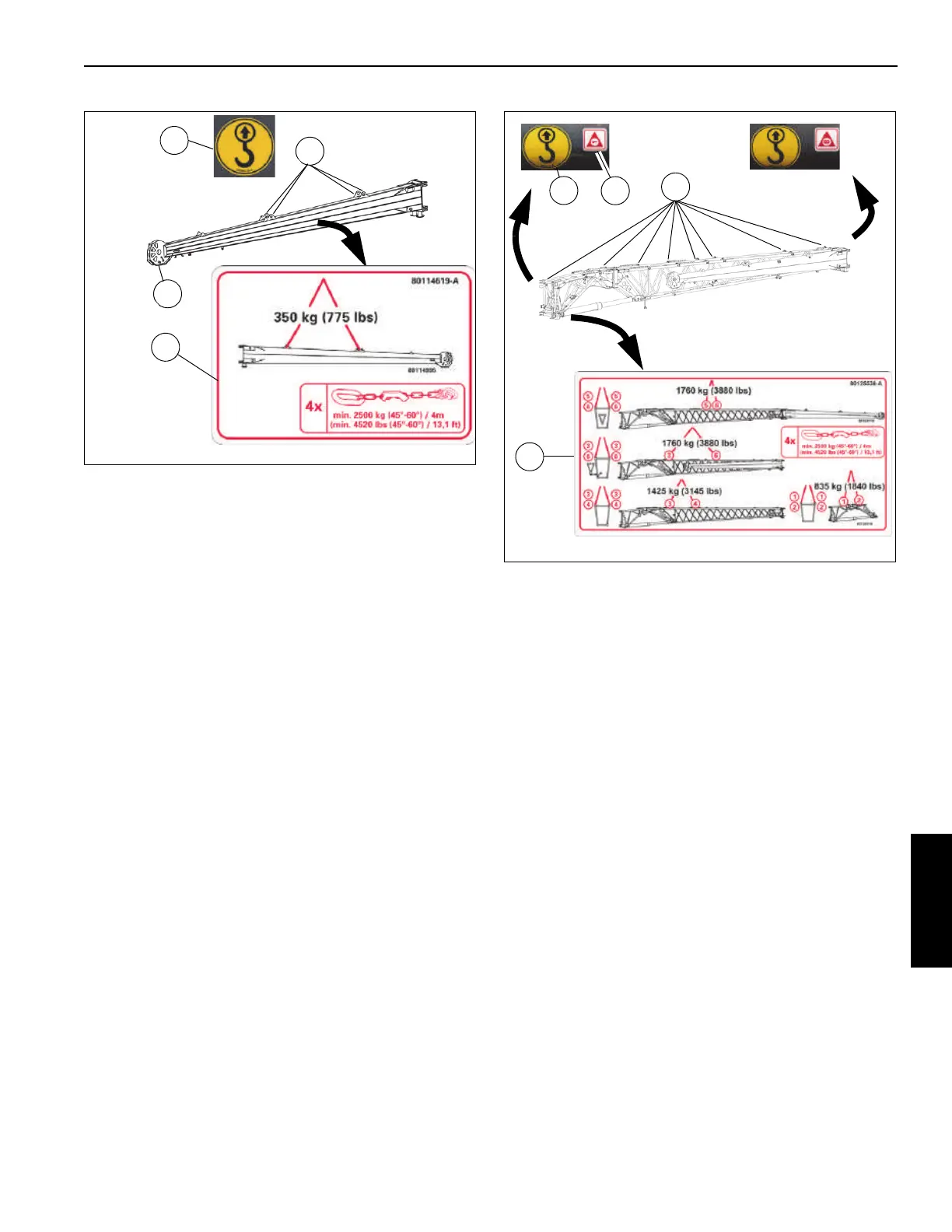
Boom Extension Base Section
The boom extension base section features eight attaching
points on each side (16 total) (1, Figure 5-35). Decals show
the attaching points (2). The attaching point decals are
numbered 1 through 8 (3). The Transportation and Lifting
decal (4) shows the different supported lifting configurations:
• Boom extension base only
• Boom extension base with fly section deployed
• Boom extension base with fly section stowed
Use the Transportation and Lifting decal to determine which
attaching points to use. The Transportation and Lifting decal
also shows required minimum lifting gear.
About the Boom Extension Group in the
ODM
Figure 5-36 shows the Boom Extension screen in the ODM.
Table 5-4 describes the icons on the Boom Extension
screen. For more information about the Alerts Area, Active
Screen Indicator Area, and Status Bar, see Using the
Operator Display Module (ODM), page 4-72.
1
4 Places
FIGURE 5-34
2
4
3
9978
9979
9980
FIGURE 5-35
16 Places
1
2
3
4
9981
9982
9983
9984

 Loading...


