OPERATING PROCEDURES GRT9165 OPERATOR MANUAL
4-108 Published 7-23-2020, Control # 668-02
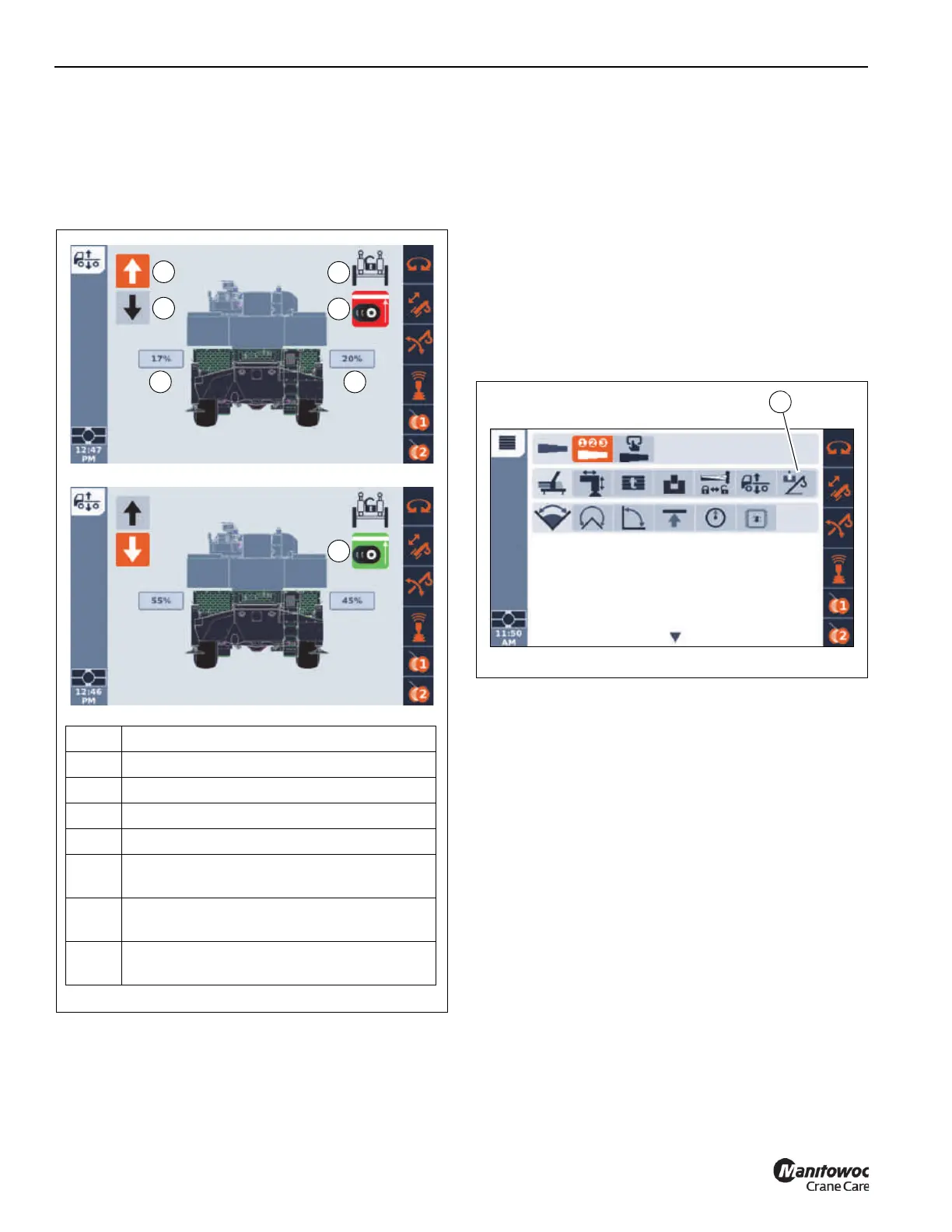
5. With focus on the Lower Suspension icon, press and
hold the Jog Dial or the OK button.
The left and right side suspension will begin to lower.
6. Release the Jog Dial or OK button when both the Left
and Right Side Suspension Height indicators (5 and 6,
Figure 4-112) are at the desired height.
As previously indicated, the suspension is at the desired
travel height when the Suspension Ride Height Status
Indicator (7, Figure 4-112) appears green. Depending on the
terrain the crane is sitting on, it may not be possible to adjust
the suspension such that the Suspension Ride Height Status
Indicator (7, Figure 4-112) appears green. In this condition,
first make sure a crane wheel is not raised up on a curb or
rock, then adjust the suspension such that the two
suspension percentages (3, 4, Figure 4-112) are centered
around 50%.
Boom Removal/Installation
Select the Boom Removal/Installation icon (1, Figure 4-113)
under the Crane Function Menu Group to show the Boom
Removal/Installation function screen.
Item Description
1 Raise Icon
2 Lower Icon
3 Left Suspension Height
4 Right Suspension Height
5
Suspension Ride Height Status Indicator (red
- suspension not at ride height)
6
Axle Oscillation Status Indicator
(locked/unlocked)
7
Suspension Ride Height Status Indicator
(green - suspension at ride height)
FIGURE 4-112
9902-17
1
2
3 4
5
6
9902-16
7

 Loading...


