5-70 Published 7-23-2020, Control # 668-02
SET-UP AND INSTALLATION GRT9165 OPERATOR MANUAL
a. Hold the handle (1, Figure 5-57) and remove the
retaining clip (2) and pin (3).
b. Raise the mast (4). Make sure the connecting point
holes are aligned.
c. Insert Pin (3). Secure the pin with retaining clip (2).
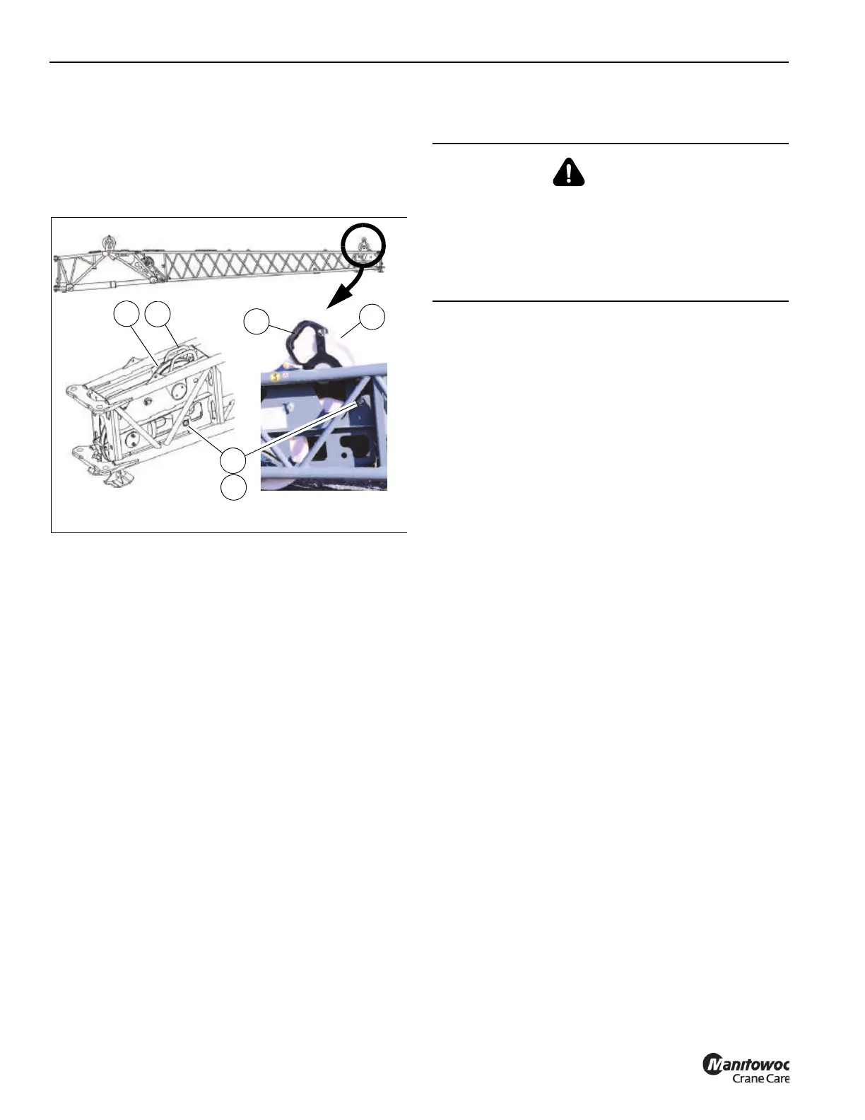
22. Raise the front mast assembly as follows:
a. Hold the handle (1, Figure 5-58) of the mast sheave
assembly (2). Remove retaining clip (3) and pin (4).
b. Raise the mast assembly (2) until the connecting
holes are aligned.
c. Insert pin (4) and secure with retaining clip (3).
23. Reeve the hoist rope. For more information, see
Reeving the Hoist Rope, page 5-77.
24. Remove the anti-two block switch from the main boom
nose. For more information, see Anti-Two Block (A2B)
Switch, page 5-32. Install anti-two block switch on the
end of the boom extension. For more information, see
Anti-Two Block Switch on the Boom Extension, page
5-79.
25. (Optional) Install the anemometer and boom position
light assembly. For more information, see Anemometer/
Boom Position Light (Optional), page 5-88.
Stowing the 10.9 m Boom Extension Base
Section Only
Use the following procedure to stow the boom extension
base section to the side of the main boom.
NOTE: This procedure the assumes only the boom
extension base section is deployed and the fly
section is secured to the side of the main boom.
NOTE: The boom extension base section cannot be
stowed if the fly section is not first stowed on the
side of the main boom.
1. Make sure the crane is set up on fully extended
outriggers. For more information, see Using the
Outriggers, page 4-21.
2. Make sure the counterweight is installed. For more
information about installing the counterweight, see
Counterweight Removal and Installation, page 5-12.
3. Retract and lower the boom to horizontal.
4. (Optional) Remove the anemometer and boom position
light assembly. For more information, see Anemometer/
Boom Position Light (Optional), page 5-88.
5. Remove the anti-two block switch from the end of the
boom extension. For more information, see Anti-Two
Block Switch on the Boom Extension, page 5-79. Install
the anti-two block switch on the main boom nose. For
more information, see Anti-Two Block (A2B) Switch,
page 5-32.
6. Remove the hoist rope from the boom extension base
section sheaves. For more information, see Reeving the
Hoist Rope, page 5-77.
7. If necessary, adjust the boom extension offset to 0°
depending on the type of boom extension:
• If stowing a mechanical boom extension, make sure
the offset is set to 0°. For more information, see
Setting a Manual Offset Angle of 0°, 15°, 30°, or 50°,
page 5-78.
or
• If stowing an optional hydraulic boom extension,
make sure the angle indicator (1, Figure 5-59) is
aligned. If the arrows are not aligned, adjust the
Lowered Position Raised Position
FIGURE 5-58
1
1
2
3
4
2
9912
9913
10004
DANGER
Boom Extension Hazard!
To avoid death or serious injury, follow procedures and
cautions in the Operator and Safety Manuals and decals
during erection, stowage and use of boom extension.
Install and secure all pins properly and control boom
extension movement at all times.

 Loading...


