Grove Published 7-23-2020, Control # 668-02 4-39
GRT9165 OPERATOR MANUAL OPERATING PROCEDURES
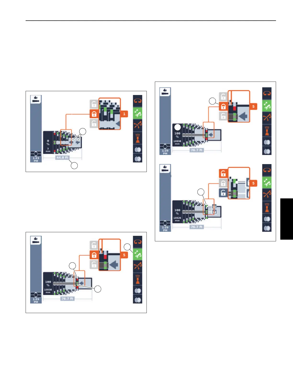
Telescoping
If the requirements for telescoping are met, the symbol (2,
Figure 4-32) is shown.
Move the control lever in the desired telescoping direction.
The display (1, Figure 4-32) shows the current extended
length of the boom.
The current telescope diagram on the display will change
continually.
Locking the Tele Section
Every telescopic section can be locked at the fixed lengths,
refer to Main Boom Fixed Length, page 4-33.
Prerequisites
Telescoping mechanism on – symbol (3, Figure 4-33) green
Telescopic section unlocked – symbol (1) red
Telescoping cylinder locked – symbol (2) green.
Lock
1. Telescope to the desired fixed length, e. g. telescopic
section (1, Figure 4-34) 1 to 100%.
If the symbol (3) is orange, the telescopic section can be
locked.
2. Select the symbol (3).
3. Confirm the selection – the locking pins will extend –
symbol (2) green.
Telescoping with Semi-automation
When telescoping with semi-automation (or the semi-auto
mode), the operator enters, on the Operator Display Module
(ODM), the pinning location for each of the boom sections (a
target or requested “tele picture”). If this pinning
configuration is accepted by CCS, then the controller is used
to move the boom sections to the pre-determined
configuration. The telescoping cylinder moves between the
boom sections automatically as needed.
NOTE: The entered boom configuration (“tele picture”)
does not have to be completed for normal
operation of the boom. For instance, if the
requested boom configuration is 100-100-0-0-0,
and just the T2 section is locked at 100% (T1
section still at 0%), then the boom can be operated
as if the configuration 0-100-0-0-0 was entered.
FIGURE 4-34
10085-17
1
10085-19
2
3

 Loading...


