OPERATING PROCEDURES GRT9165 OPERATOR MANUAL
4-42 Published 7-23-2020, Control # 668-02
configuration (or “actual tele picture”). This can be
understood as what the boom looks like “now” (but as
mentioned above the operator must be aware of the physical
boom to compare to these values). As the boom is operated
this computed boom configuration will change (just as the
schematic graphic for the boom system will change on the
display). But the operator should realize that the requested
final boom configuration will not be changing as the boom is
operated (it is the final destination for the boom motion).
Third, there is a list of percentages on the left (0%, 50%,
89%, 100%) (5). These percentages are the available
pinning locations for the boom sections. They represent an
extent of the distance along the next larger boom section
where the boom section can be pinned - i.e. locked to the
next larger and encompassing boom section. The 100% is
not the extreme end of the next larger boom section, but the
farthest available pinning location (there will always be some
overlap between boom sections). The list of percentages are
command buttons in the control system interface; a value
can be highlighted, and then an Enter button used to actually
select the value in the list. When an Enter button is used in
this manner, it sets all the values for the boom sections for
the requested final boom configuration to that value. For
example, if Enter is used on the 50% button, then all the
values in the top row of the display will be set to 50/55 (thus
requesting the final boom configuration of 55-55-50-50-50).
Semi-auto Mode Basic Operating Procedures
The following steps would be expected for extending the
boom in Semi-auto Mode:
• Enter the Semi-auto screen on the Operating Display
Module. The icon for this screen is (1) Figure 4-38.
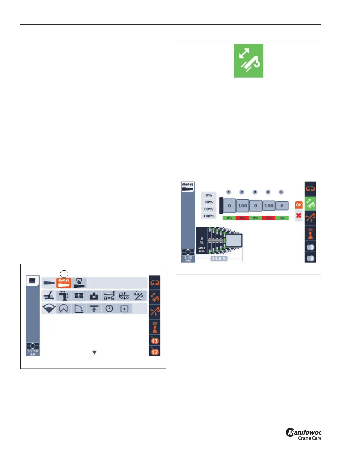
• Verify that the telescoping function is enabled. This is
confirmed by the green background for the icon for the
telescoping function in the right margin area of the
operating display. Refer to Figure 4-39.
• Using the ODM, enter the values for the requested final
boom configuration (such as 0-0-0-100-100).
• Using the ODM, the Enter button is used for the OK
shown on the screen. This sends the requested data to
the control system. If this configuration is considered
acceptable, a check-mark will be shown below the OK
(as is seen in Figure 4-37). If the configuration is not
considered acceptable, a red X will be shown instead of
the check-mark (Figure 4-400). As an example, a
requested final boom configuration of 0-100-0-100-0 is
not allowed (the T3 section was “skipped” for having a
non-0% pinning location).
• Depending on the current location of the telescoping
cylinder, the cylinder may need to move to a different
boom section. If this is needed, the automated motions
will immediately occur.
• Once the telescoping cylinder is considered locked to
the boom section that is to be first moved (T2 in the
current example) by the control system, the boom
section will be unlocked (this is an automated action).
• Once the boom section is unlocked, the telescoping
direction arrows (1), as shown in Figure 4-37, will
appear.
• With the arrows present, the operator can telescope the
first boom section to be moved (T5 in this example).
• The operator uses the telescope controller to extend the
boom section. The boom motion will automatically be
stopped at the 100% pinning location and the right arrow
will be blinking. If the telescope controller is used in the
extend direction for at least 1 second, then the boom

 Loading...


