5-86 Published 7-23-2020, Control # 668-02
SET-UP AND INSTALLATION GRT9165 OPERATOR MANUAL
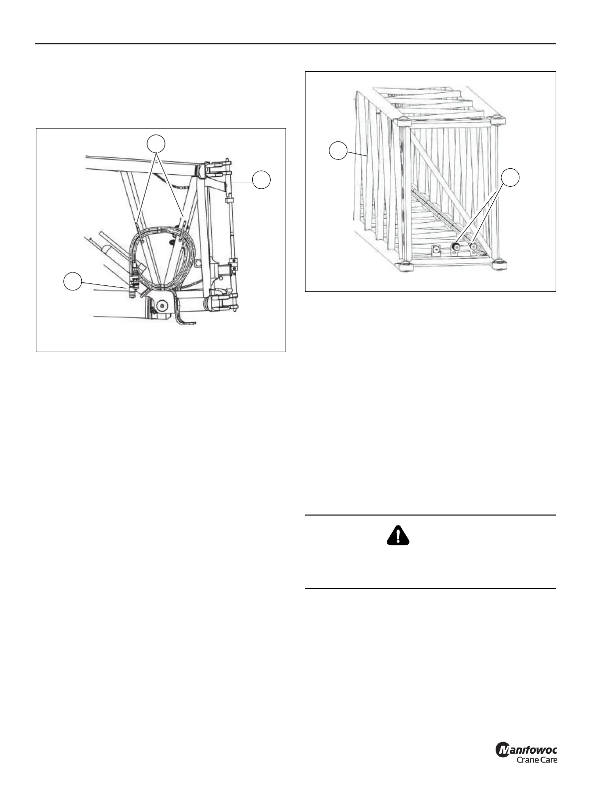
Connecting the Boom Extension Hydraulics
to the Lattice Insert
1. Remove the long hoses (1, Figure 5-74) from the
holders (2) on the boom extension (3).
2. Remove the protective caps from the hoses (1).
3. Route the hoses (1, Figure 5-74) to the front of the lattice
insert (1, Figure 5-75).
4. Remove the protective caps from hydraulic hose
connectors (2) on the lattice insert (1).
5. Connect the boom extension hoses (1, Figure 5-74) to
the hydraulic hoses on the lattice insert (2, Figure 5-75).
Disconnecting the Boom Extension
Hydraulics from the Lattice Insert
1. Disconnect the boom extension hoses (1, Figure 5-74)
from the hydraulic connectors (2, Figure 5-75) on the
lattice insert (1).
2. Install protective caps on all hose ends.
3. Secure the boom extension hoses (1, Figure 5-74) to the
hooks (2) on the boom extension (3).
AUXILIARY SINGLE SHEAVE BOOM NOSE
The following sections describe how to install, remove, and
rig the auxiliary single sheave boom nose.
NOTE: The auxiliary single-sheave boom nose assembly
weighs approximately 185 kg (408 lbs).
DANGER
Crushing Hazard!
During installation and removal, always use the proper
equipment with sufficient load bearing capacities.

 Loading...


