OPERATING CONTROLS AND FEATURES GRT9165 OPERATOR MANUAL
3-62 Published 7-23-2020, Control # 668-02
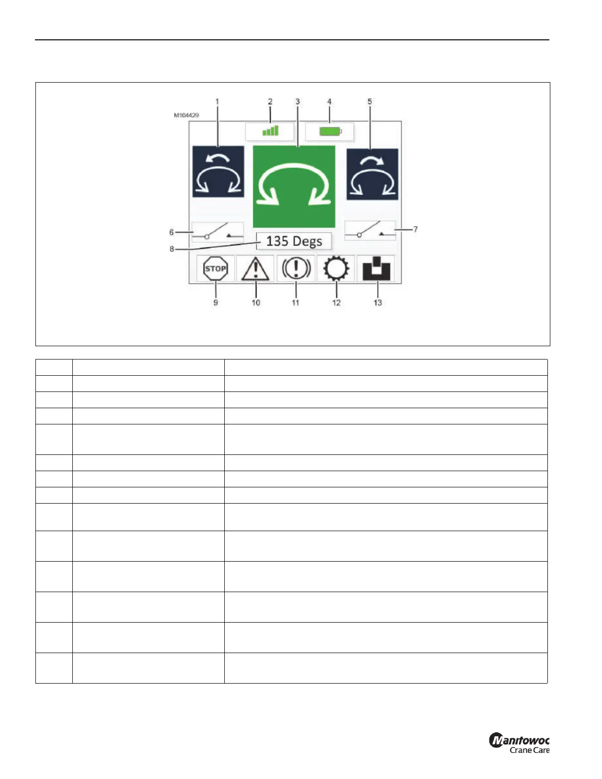
Display Components
Item Component Description
1 Left Motion Command Indicator Depicts the operation that is controlled by the left side motion button
2 Transmission Strength Indicator More bars = greater strength, and vice versa
3 Function Screen Indicator Depicts the function that is being operated (swing in this example)
4 Battery Pack Power Indicator
Green = fully charged
Amber = discharging
5 Right Motion Command Indicator Depicts the operation that is controlled by the right side motion button
6 Left Enable Indicator White = enable button is not pushed (function cannot be operated)
7 Right Enable Indicator Green = enable button is pushed (function can be operated)
8 DEG or RPM Indicator
When applicable, shows the position of the superstructure in degrees or the
rotational speed of the selected motion
9 E-Stop Indicator
White = E-Stop button pulled out (operation is allowed)
Red = E-Stop button pushed in (operation is not allowed)
10 Crane Fault Indicator
White = no active crane fault exists (operation is allowed)
Red = active crane fault exists (operation is not allowed))
11 Parking Brake Indicator
White = parking brake is applied (operation is allowed)
Red = parking brake is released (operation is not allowed)
12 Transmission Indicator
White = transmission is in neutral (operation is allowed)
Red = transmission is in gear (operation is not allowed)
13
360° Swing Lock Indicator
(Optional)
White = swing lock is engaged
Red = swing lock is disengaged
FIGURE 3-54
Example – Swing Functional Screen

 Loading...


