OPERATING PROCEDURES GRT9165 OPERATOR MANUAL
4-40 Published 7-23-2020, Control # 668-02
The operator can just stop the telescoping function
with the boom at 0-100-0-0-0.
If the boom is desired to be fully or partially
retracted after just reaching 0-100-0-0-0 (and when
100-100-0-0-0 had originally been entered), the
operator can just reverse the direction of the
controller and the boom will retract. That is, it is not
necessary to enter a boom configuration of
0-0-0-0-0 to retract the boom. The entered boom
configuration (target or requested “tele picture”) is
ALWAYS only a final destination or configuration.
The controller is ALWAYS used to indicate
extending or retracting the boom itself, NEVER to
indicate the extending or retracting of the
telescoping cylinder. The allowed motion for the
boom with the controller is indicated by arrows
shown on the display. The telescoping direction
arrow to the right is always extending the boom.
The telescoping arrow to the left is always
retracting the boom.
NOTE:
• Switch on the telescoping mechanism, refer to Switching
On the Telescoping Mechanism, page 4-33.
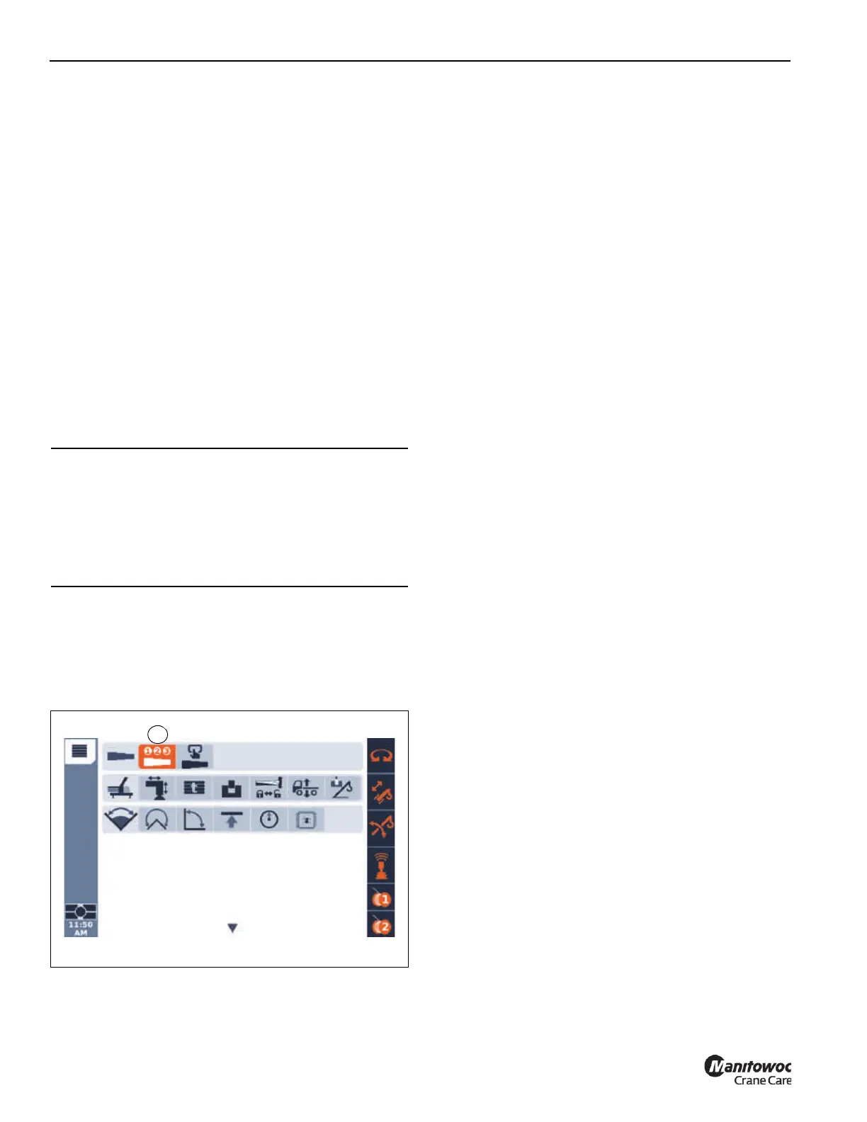
• Open the Telescoping semi-automation menu
(1, Figure 4-35).
Semi-automatic Telescope Mode
Introduction
The Semi-auto Mode is typically the standard method for
telescoping the pinned boom.
It is important to understand that a pinned boom has a
telescoping cylinder that can disconnect and reconnect
(unlock/lock) to boom sections, as well as disconnect and
connect (unlock/lock) boom sections to each other. This is
accomplished by a pinning mechanism or pinning “head” at
the near end of the barrel of the telescoping cylinder (the rod
is fixed to the base section and the barrel extends within the
boom). This pinning mechanism has a set of sensors and an
electronic module to communicate with the crane control
system. Using these sensors, as well as a precision length
sensor for the location of the telescoping cylinder within the
boom, the crane control system commands the pinning
mechanism to perform the locking operations. The
Semi-auto Mode is the simplest approach to operating the
pinned boom, since it automatically handles the most
complicated aspects of the pinning.
It is important to realize that the control system is performing
automated motions within the boom at some points in the
telescoping process. At other times the operator is able to
move the boom components. Then the automated motions
can occur once again after the operator has indicated the
appropriate next action for telescoping the boom.
The Semi-auto screen of the operating display (refer to
Figure 4-36) shows a graphic schematic near the bottom of
the screen that indicates the current status of the boom
computed by the control system (however the operator must
continue to monitor the status of the physical boom to
compare with this schematic). In Figure 4-36, there is a
100% (1) shown for the position of the telescoping cylinder
(above the 10571 mm distance value). The graphical
representation of the telescoping cylinder rod protrudes
horizontally from the left end of the schematic (near item 1).
The end of the graphical representation of the rod at the T4
boom section which is at the 100% pinning location. The
slightly larger rectangular entity at the right end of the
telescoping cylinder rod represents the pinning mechanism.
CAUTION
Boom Damage!
When a boom section is first unlocked, the boom section
may automatically extend 50 mm (2 inches). The operator
must be aware of this motion and have the crane in a
position to anticipate this motion and prevent contact with
nearby objects.

 Loading...


