Home
Manitowoc
Construction Equipment
Grove GRT9165
Manitowoc Grove GRT9165 User Manual
5
of 1
of 1 rating
476 pages
Give review
Manual
Specs
To Next Page
To Next Page
To Previous Page
To Previous Page
Loading...
Grove
Published 7-23-2020, Control # 668-02
3-43
GRT9165 OPERATOR MANUAL
OPERATING CONT
ROLS AND FEATURES
3
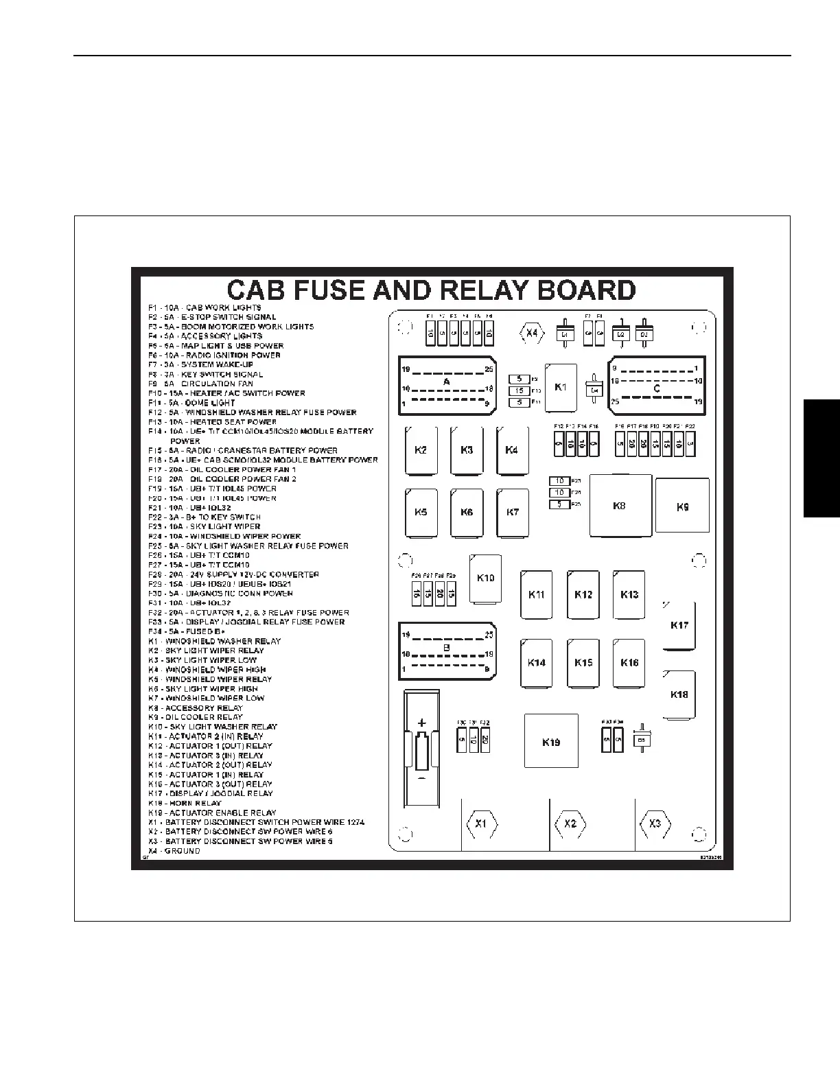
Fuse
and Relay
Panel –
Cab
The Fuse
and Rela
y
Panel (
7,
Figure 3-30) is
located behind
the operator seat
in the right side upper co
mpartmen
t (as
seated
in the
operator
seat).
The cab fuse and re
lay panel contains the fuses and rela
ys
listed in
Figure 3-31.
FIGURE 3-31
9904
116
118
Table of Contents
Table of Contents
5
Section 1
17
Customer Support
18
New Owners
18
Noise/Vibration Test Results
19
Noise Level Test Results
19
Vibration Level Test Results
19
Serial Number Location
19
GRT9165 Crane Components
20
List of Specifications
22
General
22
Dimensions
22
Capacities
22
Transmission
22
Torque Converter
22
Engine
22
Cummins QSB 6.7L - Stage V/Tier 4F
22
Cummins QSB 6.7L - Non-Certified
22
Axles
22
Boom
23
Outriggers
23
Swivel Assembly
23
Hydraulic Pumps
23
Pump #1
23
Pump #2
23
Pump #3
23
Pump #4
23
Hoists
23
Section 2
25
Safety Messages
26
General
26
Safety Alert Symbol
26
Signal Words
26
Accidents
26
Operator Information
27
Operator Qualifications
27
Operational Aids
28
Rated Capacity Limiter (RCL) Systems
28
Anti-Two-Blocking Device
29
Working Area Limiter (if Equipped)
29
Crane Stability/Structural Strength
30
Load Charts
31
Work Site
31
Wind Forces
31
Wind Speeds
32
Determination of 3-Second Wind Gust Speed at Boom Tip Height
34
Size and Shape of the Load
34
Determining Wind Drag Coefficient (CD)
35
Maximum Permissible Wind Speed
36
Example and Sample Calculations (Non-Metric)
42
Lifting Operations
44
Multiple Crane Lifts
45
Lifting Multiple Loads
45
Tilt-Up Panel Lifting
45
Counterweight
46
Outrigger Lift off
46
Pile Driving and Extracting
46
Crane Equipment
47
Crane Inspection
47
Electrocution Hazard
47
Set-Up and Operation
48
Electrocution Hazard Devices
49
Electrical Contact
49
Special Operating Conditions and Equipment
50
Grounding the Crane
50
Personnel Handling
51
Environmental Protection
52
Maintenance
52
Service and Repairs
52
Hydraulic Fluid
52
Moving Parts
53
Before Maintenance or Repairs
53
After Maintenance or Repairs
53
Lubrication
53
Tires
53
Hoist Rope
54
Synthetic Hoist Rope
54
Wire Rope
54
Sheaves
56
Batteries
56
Super Capacitor (if Equipped)
56
General Maintenance
57
Transporting the Crane
57
Travel Operation
57
Work Practices
59
Personal Considerations
59
Crane Access
59
Job Preparation
59
Working
60
Lifting
60
Hand Signals
61
Boom Extension
63
Parking and Securing
63
Shut-Down
63
Cold Weather Operation
63
Temperature Effects on Hook Blocks
64
Temperature Effects on Hydraulic Cylinders
65
Model Specific Information
67
Hoist Platform
67
Overload Inspection
67
Boom Inspection
68
Superstructure Inspection
70
Carrier Inspection
72
Operator Cab Overview
77
Steering Wheel and Column
78
Steering Wheel
79
Standard Driving Configuration
79
Alternate Driving Configuration
79
Turn Signal Lever and Horn Controls
80
Parking Brake Switch
81
Headlights Switch
81
Drive Axle Selector Switch
81
Alternate Driving Configuration
81
Turn Signal Lever and Horn Controls
81
Hazard Lights Switch
82
Transmission Shift Lever
82
Ignition Switch
82
Steering Column Tilt and Telescope Lock Lever
83
Right Overhead Control Panel
84
Heater/Air Conditioner Fan Speed Switch
85
Heater/Air Conditioner Temperature Control Switch
85
Fresh Air/Recirculation Air Switch
85
Boom-Mounted Lights Motor Switch (Optional)
85
Boom-Mounted Lights Switch (Optional)
85
Cab-Mounted Lights Switch
85
Front Window Wiper and Washer Switch
85
Skylight Wiper and Washer Switch
85
Increment/Decrement - Start/Stop Switch
85
Heater/Air Conditioner Temperature Control
85
Engine Wait-To-Start Indicator
86
Engine Brake Switch (Optional)
86
Remote Control Enable/Disable Switch
86
Crane Function Enable/Disable Switch
86
Momentary Limit Bypass Switch (Non-CE Certified Cranes)
87
Limit Bypass Set-Up Switch (CE Certified Cranes)
87
Boom up Bypass Switch
88
Steering Reversal Switch
88
Emergency Stop Button
89
Cab Dome Light
89
Left Overhead and Side Panel
90
Coat Hook
91
USB Charging Ports
91
Auxiliary Light and Switch
91
Cell Phone Holder
91
Heater/Air Conditioner Vents
91
Right Lower Control PANEL
92
Turntable Swing Lock Pin Control Handle
93
12-Volt Outlet
93
Engine On-Board Diagnostic (OBD) Connector
93
Rated Capacity Limiter Display Module and Operator Display Module
94
Rated Capacity Limiter Display Module (RDM)
95
Operator Display Module (ODM)
95
Navigation Control Pad
95
USB Connector
96
RCL Shutdown Warning Indicator (Non-CE Certified Cranes)
96
RCL Shutdown Warning Indicator (CE Certified Cranes)
96
RCL Early Warning Indicator
96
Anti-Two-Block (A2B) Indicator
96
Swing Brake Engaged Indicator
97
Brightness Sensor
97
Internal Temperature Warning Indicator
97
Operator Seat and Armrest Controls (Dual Axis)
98
Cup Holder
100
Main Hoist - Boom Lift - Telescope - Luffing Boom Extension Controller (Dual Axis)
100
Deadman Switches (Optional) (Dual Axis)
100
Horn Button
100
Hoist Speed Toggle Switches
100
Jog Dial
100
Heater/Air Conditioner Vents
100
Main Hoist Enable/Disable Switch
100
Luffing Boom Extension Enable/Disable Switch (Optional)
101
Boom Telescope Enable/Disable Switch
101
Boom Lift Enable/Disable Switch
101
Seat Lumbar Support Adjustment Lever
101
Seat Slide Lever
101
Auxiliary Hoist Enable/Disable Switch
101
Cab Tilt Switch
101
Swing Enable/Disable Switch
102
Outrigger Extend/Retract Switch
102
Differential Lock Switch
102
Rear Steer Switch
102
Standard Driving Configuration
103
Alternate Driving Configuration
104
Free Swing Button
104
Auxiliary Hoist - Swing Controller (Dual Axis)
105
Seat Backrest Adjustment Lever
105
Seat Adjustment Control Panel
105
Armrest Adjustment Buttons
105
Seat Heat Switch (Optional)
105
Seat Headrest (Not Shown)
105
Hoist Rotation Indicators
106
Seat Switch
106
Optional Single Axis Controllers
107
Swing Controller
108
Auxiliary Hoist Controller
108
Boom Lift - Telescope - Luffing Boom Extension Controller
108
Main Hoist Controller
108
Hoist Rotation Indicators (Not Shown)
108
Foot Pedal Controls
109
Swing Brake Pedal
110
Service Brake Pedal
110
Throttle Pedal
110
Floor Mat
110
Internal Rated Capacity Limiter Light Bar (Optional)
111
Internal Rated Capacity Limiter Light Bar
111
3-View Camera Display
112
Controls and Features at Front of Cab
113
Front Windshield/Emergency Exit
114
Sun Visor
114
Grab Handles
114
Foot Rests
114
Controls and Features at Rear of Cab
115
Radio (Optional)
116
Speakers (Optional)
116
Rear Window
116
Fan
116
Fire Extinguisher
116
User Manual Holder
116
Fuse and Relay Panel - Cab
117
Buzzer
118
Maintained Limit Bypass Switch (Non-CE Certified Cranes)
118
Right Window and Skylight Window
119
Skylight Window Latch (if Equipped)
120
Skylight Sun Shade
120
Right Side Window Latch
120
Controls and Features External to the Cab
121
Outrigger Removal Control Box
121
Pin Enable Switch
121
Pin Control Switch
121
Bridging Switch (CE Certified Cranes)
121
External RCL Light Tower (Optional)
123
Strobe Light or Beacon
123
Backup Alarm
123
120V/240V Engine Block Heater and Outlet
124
Emergency Stop Buttons (Optional)
124
Battery Disconnect Switch
125
Fuse and Relay Box #1 - Carrier
126
Fuse Box #2 - Carrier
127
Cab-Mounted Working Lights
128
Motorized Boom-Mounted Working Lights
128
Ladders and Grab Handles
128
Auxiliary Ladder (Optional)
129
Remote Control Unit
130
Overview
130
Storage and Charging
131
Controls and Features
132
Programming Port
133
Power Button
133
Color Display
133
Left Side Motion Button
133
Right Side Motion Button
133
Enable Buttons
133
Emergency Stop Button
133
Outrigger Beam Button
134
Outrigger Jack Button
134
Hoist Button
134
Boom Lift Button
134
Swing Button
134
Option Button
134
Engine Button
134
Horn Button
134
Information Button
134
Escape Button
135
Status Indicator
135
Battery Pack
135
Display Components
136
Pre-Starting Checks
140
Fuel Supply
140
Engine Oil
140
Engine Coolant
140
Batteries
140
Hydraulic Reservoir and Filter
140
Hoist Rope
140
Hook Block and Overhaul Ball
140
Seats and Mirrors
140
Seat Belts
140
Safety Equipment
141
Daily Lubrication
141
Boom
141
Air Intake Restriction Monitoring (AIRM) Communications System
141
Cold Weather Operation
141
Coolant Heater
142
Radiator Shutters
142
Auxiliary Cab Heater
143
Battery Heater
143
Air Diverter
143
Super Capacitor
143
Diesel Fuel
144
Engine Operation
144
Jump Starting Hazard
144
Charging the Batteries
144
Start-Up Procedure
144
Idling the Engine
145
Engine High Idle
145
Racing the Engine
145
Exhaust System Cleaning
145
Shutdown Procedure
146
Suspension Height
146
Crane Warm-Up Procedures
147
Engine
147
Transmission
147
Hoist
147
Swing Drive and Turntable Bearing
147
Axles
148
Hydraulic Oil System
148
Driving the Crane
148
Seat Belts
148
Traveling - General
148
Traveling - Towing/Pulling
149
Traveling - Being Towed/Pulled
149
Traveling on Slopes
150
General Conditions
150
Slope Limitations - Fore/Aft Travel
150
Slope Limitations - Side Slope Travel
151
Traveling with Elevated Boom
152
Traveling with Boom Extension Erected
152
Extended Traveling
153
Traveling - Forward
153
Traveling - Reverse
154
Steering
154
Front Wheel Steering
154
Rear Wheel Steering
155
Six-Wheel Steering
155
Crab Steering
155
Four-Wheel Drive Operation
155
Differential Lock Operation
155
General
156
Operation
156
Craning Functions
156
Controller Operation
156
Proper Crane Leveling
156
Using the Outriggers
157
Setting the Outriggers Manually
157
Setting the Outriggers Using the Auto-Level Feature
158
Outrigger Monitoring System (OMS)
158
Engaging the Outrigger MID-Extend Lock Pin
159
Stowing the Outriggers
159
Swinging the Boom and Superstructure
160
Stowing the Outrigger MID-Extend Lock Pin
160
Raising and Lowering the Boom
161
Raising the Boom
161
Lowering the Boom
162
Telescoping the Boom
162
Extending the Boom
163
Retracting the Boom
164
Telescoping - Theory of Operation
164
Manual Telescoping
164
Semi-Automatic Telescoping
164
Extending with the Main Boom Configuration
164
Overview
164
Telescoping Process
165
Assignment for Display
168
Fixed Length and Intermediate Length
169
Main Boom Fixed Length
169
Main Boom Intermediate Length
169
Telescoping
169
Telescoping Sequence
169
Inspections Prior to Starting Operations
169
Switching on the Telescoping Mechanism
169
Function of the Controller
169
Switching off the Telescoping Mechanism
170
Manual Telescoping
170
Telescoping with Semi-Automation
175
Semi-Automatic Telescope Mode
176
Introduction
176
Semi-Auto Mode Basic Operating Procedures
178
Semi-Auto Mode for Shifting Cylinder Within Fully Retracted Boom
180
Semi-Auto Mode Requiring Boom to be Retracted
180
Semi-Auto Mode Screen Refresh
180
Semi-Auto Mode Warning Indications
180
Semi-Auto Mode Telescoping Function Shut-Down
181
Semi-Auto Mode Lost Boom Configuration
181
Reset Telescoping Configuration
182
Semi-Auto Mode Vs. Manual Mode
183
Boom Configurator
184
Lowering and Raising the Main Hoist Rope
186
Lowering the Main Hoist Rope
186
Raising the Main Hoist Rope
186
Lowering and Raising the Auxiliary Hoist Rope
187
Lowering the Auxiliary Hoist Rope
187
Raising the Auxiliary Hoist Rope
188
Selecting the Hoist Speed Range
188
Using the Remote Control Unit
189
Preparing for Remote Control Operation
189
Operating Remote Control
191
Superstructure Horn
191
Emergency Stop
191
Engine Start/Stop/Throttle
193
Outrigger Beams
195
Outrigger Jacks
197
Hoist Control (Main and Aux)
199
Boom Lift
201
Swing and 360° Swing Lock
203
OPT (Options)
205
Information
206
Navigating the Operator Display Module and Rated Capacity Limiter Display Module
207
Using the Operator Display Module (ODM)
208
Main Screen
209
Alerts Area
210
Active Screen Indicator Area
216
Crane Information Area
217
Crane Status Area
220
Frequently Used Quick Select Menu Area
225
Status Bar
226
Permanent Quick Select Menu Area
228
Menu Screen
229
Tele-Automation Menu Group
232
Semi-Automation Telescope Mode
232
Boom Configurator Mode
234
Crane Function Menu Group
236
Outrigger Extend/Retract
236
Counterweight Removal/Installation
242
360° Swing Lock (Optional)
242
Boom Extension Deployment/Stowage
243
Suspension Raise/Lower
243
Boom Removal/Installation
244
Working Range Limiter Menu Group
246
Introduction
246
WRL Limitations Overview
246
Accessing a WRL Limitation Screen
248
Boom Height Limitation
253
Boom Angle Limitation
255
Radius Limitation
258
Swing Angle Limitation
260
Virtual Walls Limitation
263
Emergency Program Menu Group
267
Manual Telescope Mode
267
Emergency Telescope Mode
269
Tables for Approaching the Locking Points
278
Telescoping Cylinder Boom Nose Switch
279
Faults Menu Group
280
Crane Faults
280
Engine Faults
281
Information Menu Group
282
Operating Hours
282
Software Versions
284
Legal Notice
284
User Settings Menu Group
285
Controller Curve
285
Controller Speed
288
ECO Mode
289
Exhaust System Cleaning (if Equipped)
291
Service Menu
292
Display Settings Menu Group
293
Units of Measure
293
Display Screen Brightness
293
Time Set
294
Using the Rated Capacity Limiter Display Module (RDM)
295
Enter Rigging Code
295
Entering Individual Components
295
Entering the RCL Code
299
Checks before Operating the Crane
300
Displays During Crane Operation
302
RCL Early Warning
303
RCL Shutdown
304
Limit Bypass Alert Indicators
305
Load Chart and Miscellaneous Alerts
305
Preload Check
309
Using the Load Chart
309
Stowing and Parking
311
Leaving Crane Unattended
311
Long-Term Storage
311
Section 5
313
Setup of Crane before and after Transporting
314
Hoist Camera
315
Lowering the Hoist Camera for Transport
315
Raising the Hoist Camera for Operation
315
Hoist Platform
316
Lowering the Hoist Platform Railings for Transport
316
Raising the Hoist Access Railings for Operation
316
Beacon Lights (Optional)
317
Lowering the Beacon Light for Transport
317
Raising the Beacon Light for Operation
317
Cab Mirrors
318
RCL Light Tower (Optional)
319
Retracting the RCL Light Tower for Transport
319
Extending the RCL Light Tower for Operation
319
Access Ladders
320
Raising the Access Ladder for Transport
320
Lowering the Access Ladder
320
Auxiliary Ladder
320
Stowing the Auxiliary Ladder for Transport
322
Installing the Auxiliary Ladder
322
Auxiliary Ladder Rear Maintenance Location
322
Outrigger Floats
322
Stowing an Outrigger Float for Transport
323
Removing an Outrigger Float from Stowage
323
Hydraulic Hose Drum (Optional)
323
Boom Position Indicator Light and Anemometer (Optional)
323
Auxiliary Single-Sheave Boom Nose
323
Boom Lift Cylinder
323
Installing Cable on the Hoist
323
Counterweight Removal and Installation
324
General Warnings
324
Counterweight Sections Lifting Points
324
Assembling the Counterweight for Operation
326
Disassembling the Counterweight for Transport
326
Installing the Counterweight on the Carrier Platform
328
Removing the Counterweight from the Carrier Platform
329
Installing and Removing the Counterweight On/From the Superstructure
331
Overview of the Counterweight ODM Screen
331
Automatic Mode
334
Entering Automatic Mode
334
Pausing Automatic Mode
334
Canceling Automatic Mode
334
Lowering the Counterweight on to the Carrier (Automatic Mode)
334
Installing the Counterweight on to the Superstructure (Automatic Mode)
336
Manual Mode
338
Removing the Counterweight (Manual Mode)
338
Installing the Counterweight (Manual Mode)
339
Outrigger Removal and Installation
341
Bleed Valve Operation
341
Outrigger Box Removal
341
Outrigger Box Installation
342
Anti-Two Block (A2B) Switch
344
Locking
344
Unlocking
344
Checking before Operation
344
Cranes with Main Hoist Only
344
Cranes with Main and Auxiliary Hoists
345
Hoist Rope Reeving
346
Possible Reeving Combinations
346
Quick Reeving the Hook Block
354
Reeving Hoist Rope over the Boom
354
Adjusting the Upper Head Sheave
354
Reeving/Unreeving the Hoist Rope
355
Dead-End Rigging/Wedge Sockets
356
Installing Wedge and Socket
356
Boom Extension
357
Set-Up and Installation
357
General Warnings
358
Boom Extension Configurations
358
Boom Extension Pin Interlock Mechanism
359
Front Boom Extension Mounting Pin
359
Boom Nose Installation Pins
359
Front Mounting Pin Handle
360
Boom Extension Mounting Brackets
360
Boom Extension Sensors
362
Lifting Points
362
Lattice Insert
362
Fly Section
362
Boom Extension Base Section
363
About the Boom Extension Group in the ODM
363
Accessing the Boom Extension Group in the ODM
365
Installing the Boom Extension
365
Removing the Boom Extension
368
Erecting the 17.8 M Boom Extension
369
Erecting the Fly Section
374
Stowing the Fly Section
376
Stowing the 17.8 M Boom Extension
376
Erecting the 10.9 M Boom Extension Base Section Only
379
Stowing the 10.9 M Boom Extension Base Section Only
382
Boom Extension and Lattice Insert Electrical Connections
384
Connecting Electrical Connection to Main Boom
385
Disconnecting Electrical Connection from Main Boom
385
Connecting Electrical Connection to Lattice Insert
385
Disconnecting Electrical Connection from Lattice Insert
385
Hydraulic Boom Extension Connections
385
Checking the Locking Device on the Hose Drum
385
Unlocking the Drum
386
Locking the Drum
386
Extending Hoses for Hydraulic Boom Extension Operation
386
Retracting Hydraulic Hoses for Main Boom Operation
388
Connecting the Hydraulic Hoses for Operation
388
Disconnecting Hydraulic Hoses
388
Reeving the Hoist Rope
389
Unreeving Hoist Rope
389
Offsetting the Boom Extension
389
Setting a Manual Offset Angle of 0°, 15°, 30°, or 50
390
Setting the (Optional) Hydraulic Boom Extension Offset
391
Anti-Two Block Switch on the Boom Extension
391
Boom Extension Base Section
391
Boom Extension Fly Section
392
Lattice Insert (Optional)
393
Attaching the Lattice Insert on the Boom Nose
393
Installing the Boom Extension on the Lattice Insert
395
Removing the Boom Extension from the Lattice Insert
396
Removing the Lattice Insert from the Boom Nose
397
Boom Extension-To-Lattice Insert Hydraulic Connections
397
Removing the Lattice Insert from the Boom
397
Nose
397
Connecting the Boom Extension Hydraulics to the Lattice Insert
398
Disconnecting the Boom Extension Hydraulics from the Lattice Insert
398
Auxiliary Single Sheave Boom Nose
398
Installing Auxiliary Single-Sheave Boom Nose
399
Removing the Auxiliary Single-Sheave Boom Nose
399
Rigging the Auxiliary Single-Sheave Boom Nose for Transport
399
Removing the Auxiliary Single-Sheave Boom
399
Nose
399
Rigging in Transport Position
400
Rigging in Working Position
400
Reeving the Hoist Rope
400
Anemometer/Boom Position Light (Optional)
400
Installing the Anemometer/Boom Position Light
400
Removing Anemometer/Boom Position Light
400
Installing the Anemometer/Boom Position
400
Light
400
General
404
Environmental Protection
404
Lubricants and Lubrication Intervals
404
Arctic Lubricants and Conditions
407
Arctic Conditions below -9°C (+15°F)
407
Cold Weather Package and Lubricants
407
Cylinder Rod Surface Protection
411
Wire Rope Lubrication
411
Lubrication Points
411
Cranelube
412
Cummins Oil Registration List
412
Safety
412
Drive Train
414
Steering and Suspension
424
Axle Lubrication
426
Superstructure Lubrication
428
Superstructure and Cab Tilt Lubrication
432
Outrigger Lubrication
434
Lift Cylinder Lubrication
436
Boom Lubrication
440
Hoist Lubrication
448
Hydraulics Lubrication
450
Rust Protection
452
Protecting Cranes from Rusting
452
Cleaning Procedures
452
Inspection and Repair
453
Application
453
Areas of Application
453
Other manuals for Manitowoc Grove GRT9165
Service Manual
302 pages
5
Based on 1 rating
Ask a question
Give review
Questions and Answers:
Need help?
Do you have a question about the Manitowoc Grove GRT9165 and is the answer not in the manual?
Ask a question
Manitowoc Grove GRT9165 Specifications
General
Brand
Manitowoc
Model
Grove GRT9165
Category
Construction Equipment
Language
English
Related product manuals
Manitowoc Grove GRT880
202 pages
Manitowoc Grove GRT8100
216 pages
Manitowoc Grove GRT655L
278 pages
Manitowoc Grove GRT8120
448 pages
Manitowoc Grove YB5515
134 pages
Manitowoc Grove CD3340B
362 pages
Manitowoc Grove GMK6300L
1004 pages
Manitowoc Grove YB5515-2
152 pages
Manitowoc GROVE GMK5150L
1040 pages
Manitowoc GROVE GMK 5095
286 pages
Manitowoc GROVE GMK 6400
960 pages
Manitowoc Grove GMK 5250L
958 pages

 Loading...


