5-50 Published 7-23-2020, Control # 668-02
SET-UP AND INSTALLATION GRT9165 OPERATOR MANUAL
Boom Extension Sensors
The front and rear boom extension mounting brackets
feature the following sensors:
• Rear Mounting Pin Sensor (3, Figure 5-32)—Sends a
signal to the control system when the rear boom
extension pin is extended in the rear boom extension
mounting bracket. The rear mounting pin is electrically
controlled from the ODM in the operator cab.
• Rear Side Sensor(4, Figure 5-32)—Sends a signal to
the control system when the boom extension fly section
is in the stowed position next to the boom base.
• Front Mounting Pin Sensor (7, Figure 5-32)—Sends a
signal to the control system when the front boom
extension pin is extended in the front boom extension
mounting bracket. The front mounting pin is electrically
controlled from the ODM in the operator cab. For more
information, see Boom Extension Pin Interlock
Mechanism, page 5-47.
• Front Side Sensor (8, Figure 5-32)—Sends a signal to
the control system when the boom extension is in the
stowed position next to the boom base.
• Boom Nose Sensor (5, Figure 5-32)—Sends a signal to
the control system when the boom extension is in the
deployed position.
Signals from the sensors appear in the ODM in the operator
cab to inform the operator about the status of the boom
extension.
Lifting Points
The following sections describe the sling attaching points for
the boom extension sections.
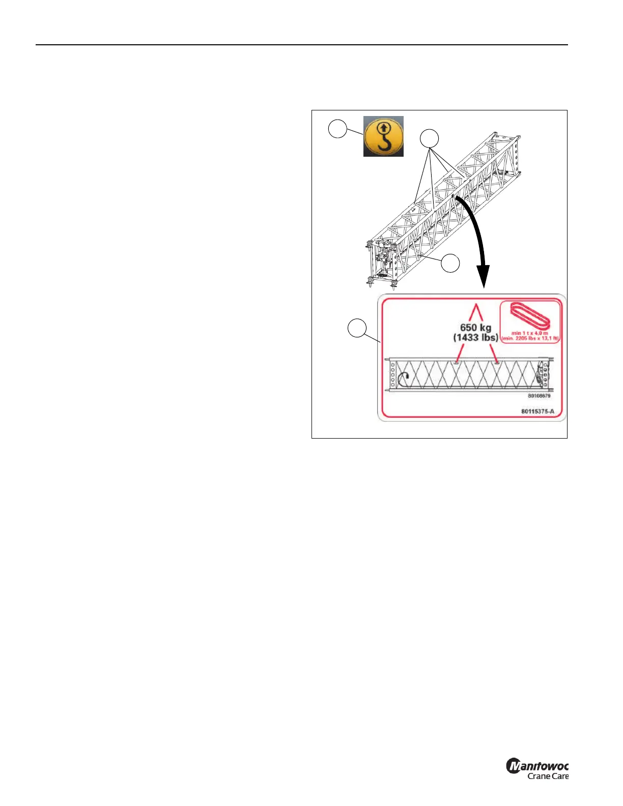
Lattice Insert
The lattice insert features four fixed attaching points (1,
Figure 5-33). Decals (2) mark the attaching points. The
weight information decal (3) shows information about the
lattice insert weight and necessary lifting gear. Tie a tag line
to a lacing (4) as necessary to guide the lattice insert during
lifting operations.
Fly Section
The fly section features four fixed attaching points (1,
Figure 5-34). Decals (2) mark the attaching points. The
weight information decal (3) shows information about the
lattice insert weight and necessary lifting gear. Tie a tag line
to the end of fly section (4) as necessary to guide the section
during lifting operations.
4 Places
FIGURE 5-33
1
2
3
4
9975
9976
9977

 Loading...


