Grove Published 7-23-2020, Control # 668-02 4-47
GRT9165 OPERATOR MANUAL OPERATING PROCEDURES
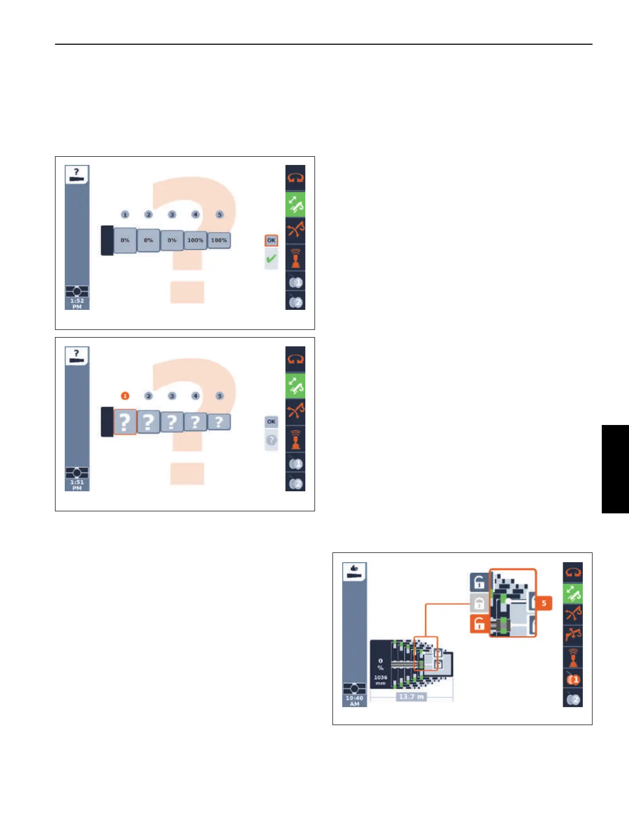
OK in the screen. If the control system confirms this
boom configuration, then a check-mark appears below
the OK (as in Figure 4-50). Otherwise, the question
mark shown under the OK (as in Figure 4-51) will
remain; in this case, the operator should exit the screen
and repeat an attempt to enter the actual boom
configuration.
Semi-auto Mode vs. Manual Mode
The pinned boom can also be controlled with a Manual
Mode. Although the Manual Mode allows some additional
capabilities, the Manual Mode still requires some automated
motions. The Manual Mode screen includes the same
schematic graphical representation of the boom, and it uses
the same dots indication for automated motions (as shown in
Figure 4-35), as well as the telescoping direction arrows for
operator control (as shown in Figure 4-36).
The following outlines differences between the Semi-auto
Mode and the Manual Mode:
• The Manual Mode screen does not show the final boom
configuration values (“target tele picture” or “actual tele
picture”). In Manual Mode, the operator requests lock
and unlock procedures and telescopes boom sections to
desired pinning locations without an initial indication of
the final destination. However, the control system
internally still creates such a final boom configuration for
the instance where the operator changes to the
Semi-auto Mode after using the Manual Mode. The
control system sets the final destination for all boom
sections not yet moved to 100%. Thus, when changing
from Semi-auto Mode (where the operator may have
entered 55-55-50-0-0) to Manual Mode (where only
boom sections T1, T2, and T3 were operated), and then
changing back to Semi-Auto Mode, the Semi-auto
screen can show 100-55-50-0-0 (thus the control system
automatically changed the destination of T1 from 55% to
100%). This is expected behavior. The operator can use
the Semi-auto screen to change the 100% back to 55%,
and in some cases, the boom can continue to be
operated (but in other cases, the boom may have to be
fully retracted first).
• The Manual Mode shows an expanded view of the
telescoping cylinder pinning mechanism with the same
unlock icons and a lock icon, as seen in Figure 4-52
(instead of the requested final boom configuration
values for the Semi-auto Mode). When one of the unlock
or lock icons becomes available to be selected (changes
from the basic gray color to the focus color), then the
operator can request the unlock command or the lock
command. The top unlock icon is for the boom section
unlocking, and at the proper time the lock icon would be
used to again lock the boom section (the lock icon will
become available as a command when the control
system allows it). The bottom unlock icon is for the
telescoping cylinder unlocking, and again at the proper
time the lock icon would be used to again lock the
telescoping cylinder (again the lock icon will become
available as a command when the control system allows
it). There is only one lock icon since the pinning
mechanism is designed to either unlock the boom
section or the telescoping cylinder (but not both at the
same time). In this manner, the boom configuration and
pinning locations are “built up” by the operator as the
boom is operated.

 Loading...


