Grove Published 7-23-2020, Control # 668-02 5-29
GRT9165 OPERATOR MANUAL SET-UP AND INSTALLATION
When the locking pins are locked, the counterweight is
installed.
14. Update the RCL code as needed for a configuration that
includes the counterweight. For more information, see
Enter Rigging Code, page 4-159.
OUTRIGGER REMOVAL AND
INSTALLATION
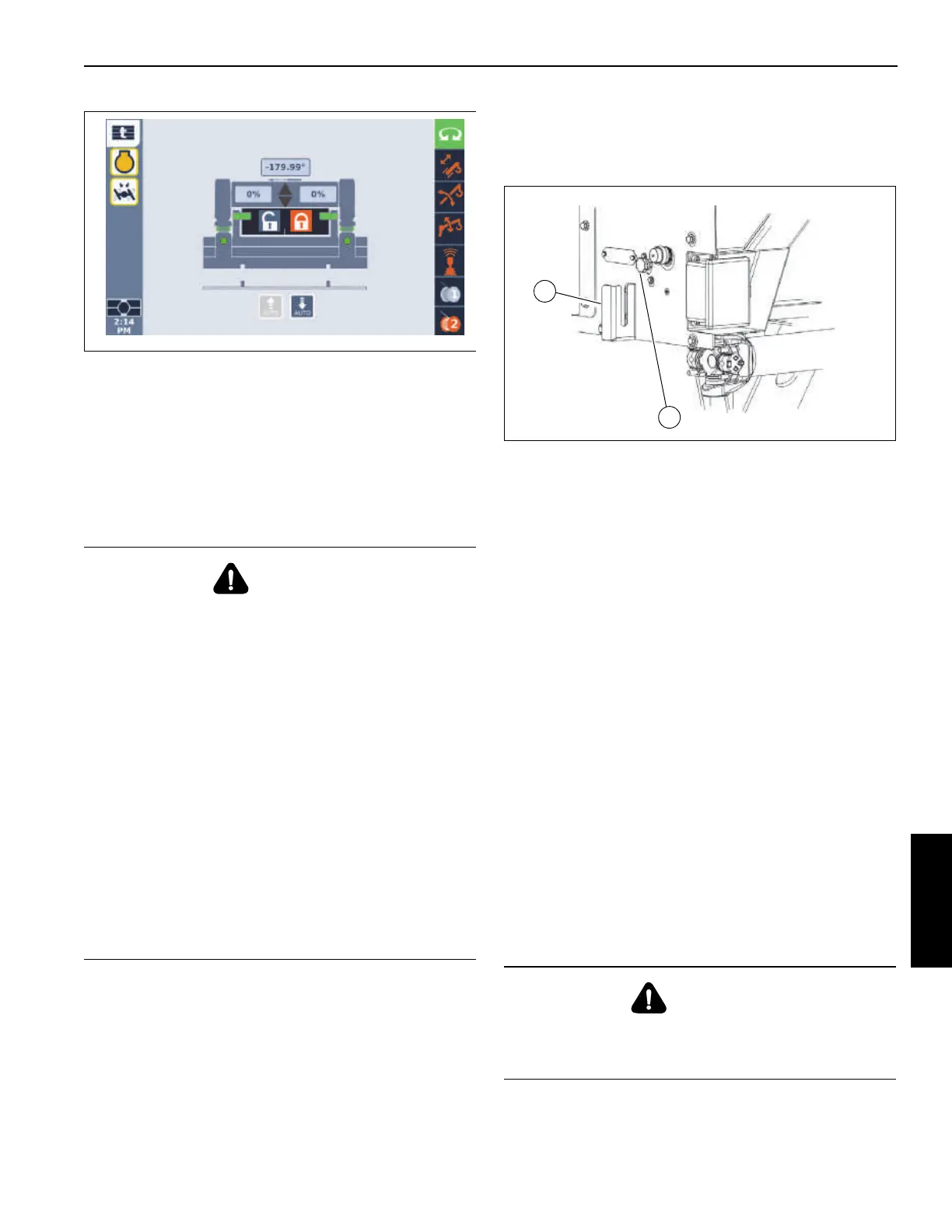
Bleed Valve Operation
The manual pressure bleed valve (1, Figure 5-17) is located
on the back of the right rear fender. The purpose of the valve
is to reduce the effort required to separate and connect the
hydraulic quick disconnect couplers when removing or
installing the front and rear outrigger boxes.
The hydraulic hoses on each outrigger box also feature
bleed fittings (9, Figure 5-19). Use these bleed fittings relieve
pressure when installing the outrigger box after the box has
been sitting in the sun.
1. Shut off the engine.
2. Turn the handle counterclockwise to open the bleed
valve.
3. Wait approximately 20 to 30 seconds.
4. As necessary, separate or connect the quick
disconnects.
5. Immediately close the bleed valve.
6. Restart the engine if necessary.
Outrigger Box Removal
NOTE: The outrigger box assembly weighs approximately
9427 lb (4276 kg).
1. Remove the counterweight. For more information, see
Counterweight Removal and Installation, page 5-12.
2. Program the RCL for the On Rubber, 360° Rotation, No
Counterweight (code 9810) load chart.
3. Remove the quick release pins (2, Figure 5-19) from the
ends of each of the pinning cylinder rod ends (3).
4. Using the crane boom for the lifting operation, fasten
lifting slings to the lifting lugs (4).
5. Lift the outrigger box enough to remove the pressure off
of the ends of the pinning cylinder rod ends (3).
DANGER!
Tipping Hazard
• Lifting the outrigger box must be done sitting on the
tires.
• While lifting the outrigger box on rubber, the Crane
must be positioned on a firm, level surface.
• When lifting the outrigger box while on rubber, the
boom must be limited to 8 m (25 ft) maximum radius.
• No counterweights are to be installed on the
superstructure if swinging over the side on rubber.
• With no load, do not exceed a 9 m (30 ft) load radius
over sides of machine since a loss of stability could
occur, causing a tipping condition. To lower boom into
a horizontal position, boom must be swung over the
front of the machine and the RCL bypass activated.
• After one outrigger box is installed, do not swing the
boom over that end of the machine while installing the
other outrigger box.
CAUTION!
Do not activate any switches on the control in Figure 5-18
or the remote control until you are thoroughly familiar with
the outrigger box installation and removal procedure.

 Loading...


